
Automated Soldering Equipment for Wire-Core Square Pressing and Resistor Welding Cell
Automated Soldering Equipment for wire-core square pressing, resistor co-welding and secondary flat welding in a compact 1,400 x 800 x 1,900 mm cell.
See how we designed this project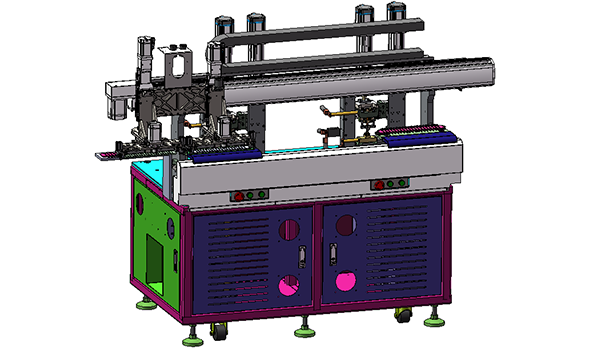
Project Snapshot
- Client Type
- Wire Harness and Sensor Manufacturer
- Timeline
- Project dated 2025-05-13
- Deliverables
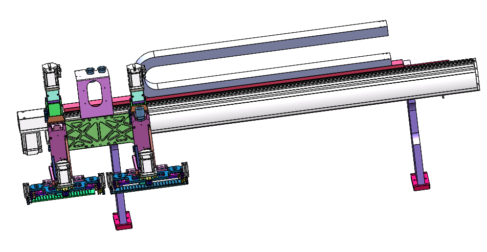
- Wire-board handling and transfer station
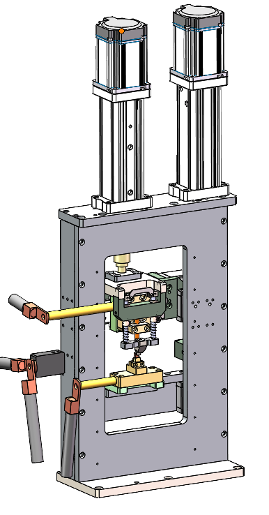
- Wire-core square pressing module
- Single-channel resistor welding process
- Secondary flat welding integration
Background
Project scope
We designed a compact electronics sensor wire-board processing cell for small-head and 58-ohm resistor welding work. The equipment combines wire-core square pressing, resistor co-welding and secondary flat welding in one process route. That makes the scope an Automated Soldering Equipment application for wire-core square pressing and resistor welding.
The equipment overview defines compatibility with incoming parts 13 to 14 mm long, with a maximum head size of 3 mm. It also defines 24# and 26# wire compatibility, including paired wire and separated wire, with wire lengths from 120 to 1,500 mm and exposed wire length from 15 to 30 mm.
Challenge
Manual board loading with controlled forming
The process had to keep manual loading and unloading of the wire board while still controlling the forming and welding sequence inside the machine. That means the board transfer, pressing location, welding location and finished-board removal all need predictable positioning.
Dimensional and welding requirements
The finished component target includes a formed head dimension of 9 to 13 mm. After welding, the component head extends 25 to 40 mm from the half side of the wire board. These dimensions create a tight relationship between board locating, press-head alignment and downstream welding access.
Approach
Process sequence
We structured the flow around six steps:
- Transfer the wire board to the square-pressing station.
- Press the wire core.
- Transfer the wire board to the welding position.
- Co-weld the wire core and resistor.
- Complete secondary flat welding.
- Unload the finished board.
Machine layout
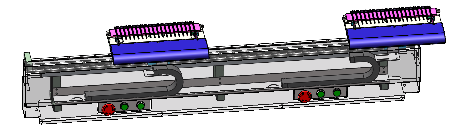
The machine envelope is 1,400 x 800 x 1,900 mm. The layout is organized around a wire-board transfer and welding group, a board handling group, two square-pressing groups and the main frame group.
For a related wire-harness sensor joining application, see our wire harness sensor automated soldering equipment case study, where wire handling, soldering access and controlled station layout are also treated as one integrated automation problem.
| Module | Confirmed role |
|---|---|
| Wire-board handling station | Moves and grips the wire board |
| Transfer and welding station | Positions the board for welding through a powered guide rail and locating fixture |
| Square-pressing station | Uses upper and lower welding-head assemblies for wire-core pressing |
| Integrated line layout | Combines wire cutting and board loading, three-station welding and secondary square-press welding |
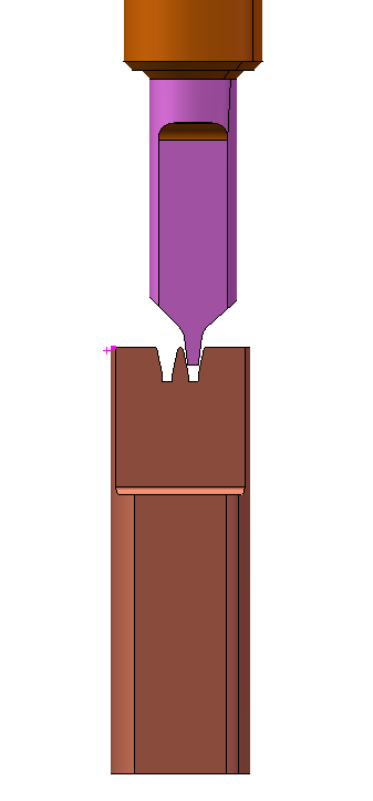
Outcome
Proposed operating result
The cell turns a manual board-handling process into a controlled pressing and welding route while keeping the operator-facing loading and unloading method simple. The listed configuration uses single-channel welding and a real-time efficiency target of 1,800 to 2,000.
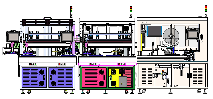
The resulting system is intended for repeatable wire-core forming before resistor welding, with defined board transfer, locating, pressing and secondary flat-welding steps inside a compact machine footprint.
Project Feedback
Share a short review of this case study or tell us what kind of automation project you want to compare it with.
No published reviews yet.