
Automated Welding for Wire Carrier Board Machine with Resistance Welding and No Tinning
Automated Welding concept for electronics wire carrier boards, combining payoff, cutting, stripping, tape bonding, component forming and resistance welding without tinning.
See how we designed this project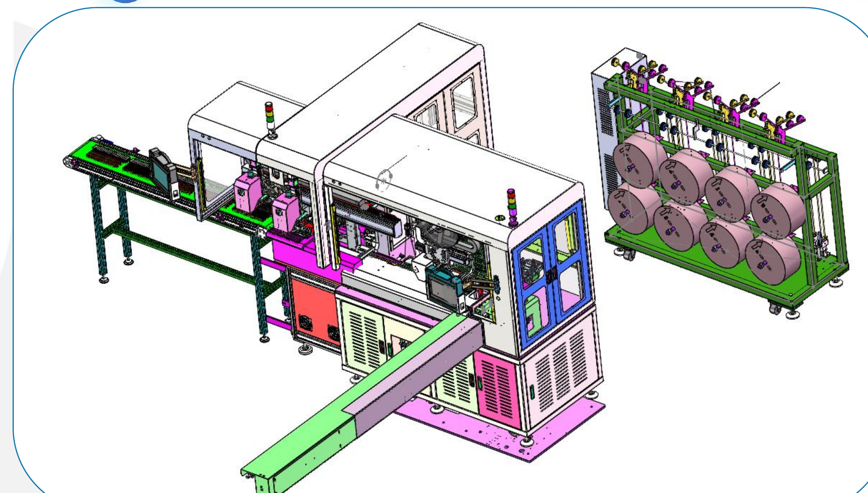
Project Snapshot
- Client Type
- Electronics Component Manufacturer
- Timeline
- Project dated 2026-03-28
- Deliverables
- Overall machine and layout concept
- Wire payoff, cutting, stripping and routing modules
- Carrier-board magazine and tape-bonding process
- Component cutting, forming and resistance-welding process
Background
Project scope
We designed an electronics component wire carrier board machine for a resistance-welding process that does not use tinning. The equipment concept combines wire payoff, wire cutting and stripping, carrier-board magazine feeding, tape bonding, component cutting/forming, welding and conveyor discharge into one line. That makes the scope an automated Welding application for wire feeding, cutting, stripping, carrier-board loading, taping, component forming and resistance welding.
The confirmed performance target is 1000 to 1200 pcs/h with 1 operator. The available project data does not include investment amount, labor-comparison data, ROI or payback period, so those figures are not claimed for this case.
Challenge
Replacing a tinning-dependent workflow
The product needs to be built through resistance welding without adding a tinning step. That makes component shape control, lead preparation, wire positioning and carrier-board transfer more important, because the welding process depends on consistent geometry and contact.
Managing wire length and carrier-board handling
The machine has to pull wire from a payoff rack, cut and strip the wire, combine it with carrier boards, bond with tape and feed the assembly into the welding section. The line also needs to support adjustable wire length from 110 to 1200 mm; when the wire length is above 1200 mm, the project layout notes that an auxiliary wire-tail arranging mechanism is required.
Approach
Machine layout
The layout includes a payoff rack, component welding machine, carrier-board machine, discharge conveyor, welding mechanism, cutting and forming mechanism, component magnetic box, tape unit, carrier-board loading magazine, wire inlet, wire arranging path, and wire cutting/stripping section.
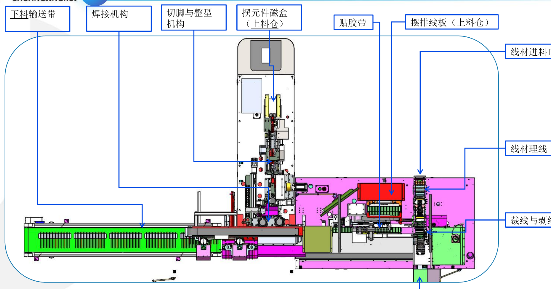
| Module | Confirmed function |
|---|---|
| Payoff rack | Wire-roll supply, adjustable rack design |
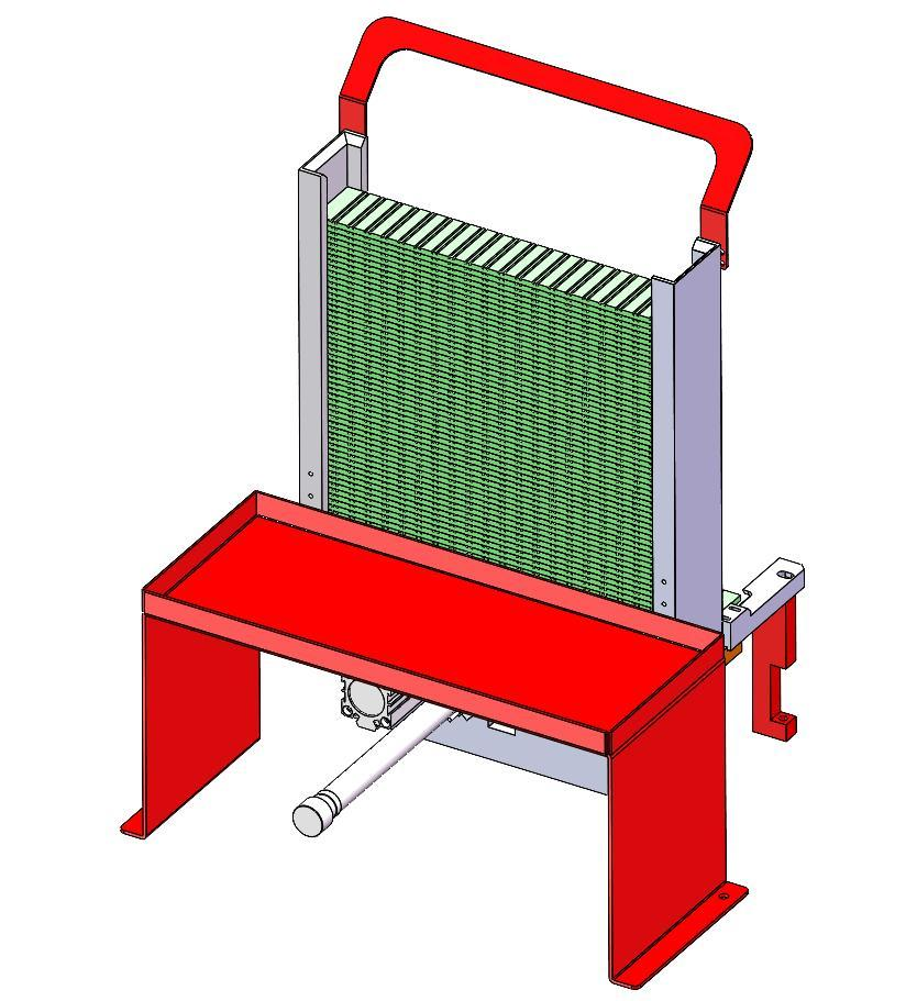
| Carrier-board loading magazine | Stores and feeds carrier boards |
| Wire inlet and wire arranging path | Guides wire into the cutting and stripping section |
| Cutting and stripping | Cuts wire and strips insulation before board assembly |
| Tape unit | Bonds carrier board and wire |
| Component magnetic box | Feeds formed components |
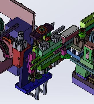
| Cutting and forming mechanism | Cuts component leads and reshapes the part before welding |
| Welding mechanism | Resistance welding without tinning |
| Discharge conveyor | Receives finished assemblies from the welding process |
Process flow
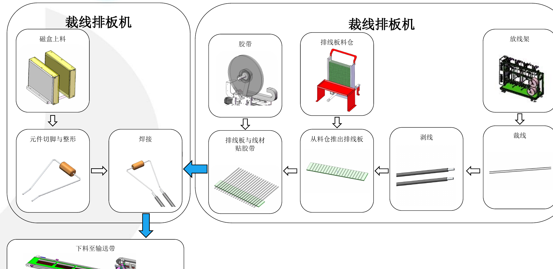
The confirmed process route is:
- Wire is supplied from the payoff rack.
- The line cuts the wire.
- The line strips the wire.
- The carrier board is pushed out from the magazine.
- The carrier board and wire are bonded with tape.
- Components are loaded from the magnetic box.
- Component leads are cut and formed.
- The component and wire assembly is resistance welded.
- Finished assemblies discharge to the conveyor.
For a closer look at this type of wire preparation and welding route, we describe the same carrier-board assembly logic in our automated welding for wire carrier board assembly article, including the payoff, cutting, stripping, taping, component forming and resistance-welding sequence.
Component forming change
The project requires a change to the component forming shape before welding. The modified target shape is intended to make the welding process simpler and more efficient. The visible dimensional callouts on the forming sketch include 12 +/- 0.5 mm, R0.65, R1.15, 14 mm, 15 mm, 17 +/- 0.5 mm and 4 mm.
Carrier-board and wire handling
The payoff rack can be modified according to project requirements and is shown with capacity for 2 to 8 wire rolls. The carrier-board magazine is shown with storage for up to 50 carrier boards.
Reference dimensions and parameters
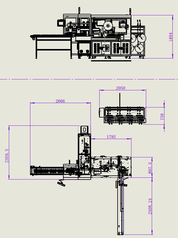
The dimension page provides layout reference values rather than a single complete envelope. The parameter table points back to the equipment outline drawing for layout reference size.
| Item | Confirmed specification |
|---|---|
| Machine height in main view | 1894 mm |
| Layout reference callouts | 2666 mm, 2050 mm, 758 mm, 1785 mm, 897.5 mm, 2359.5 mm and 2508.24 mm |
| Adjustable wire length | 110 to 1200 mm |
| Extra wire-tail handling | Required when wire length exceeds 1200 mm |
| Payoff rack capacity | 2 to 8 wire rolls |
| Carrier-board magazine capacity | Up to 50 carrier boards |
| Air supply | 0.5 to 0.7 MPa |
| Power supply | AC380V |
| Planned capacity | 1000 to 1200 pcs/h |
| Control system | HMI + PLC |
| Operator requirement | 1 operator |
Outcome
Proposed operating result
The resulting line connects wire preparation, carrier-board transfer, tape bonding, component forming and resistance welding into a defined one-operator process. The no-tinning requirement is handled by controlling wire stripping, board alignment, component shape and welding contact instead of adding a separate tinning operation.
Process value
The process value is integration: wire handling, board feeding, tape bonding, component forming, resistance welding and conveyor discharge are designed as one coordinated machine. Confirmed planning data supports a 1000 to 1200 pcs/h capacity range, AC380V power, 0.5 to 0.7 MPa air supply and HMI + PLC control. Commercial return figures are not included in the project data, so ROI is left unclaimed.
Project Feedback
Share a short review of this case study or tell us what kind of automation project you want to compare it with.
No published reviews yet.