
Automated Assembly Solutions for Single-End Wire Welding and Assembly Line
Automated assembly solutions line for single-end wire products, integrating wire cutting, board loading, welding, CCD checks, tube pushing, forming and collection.
See how we designed this project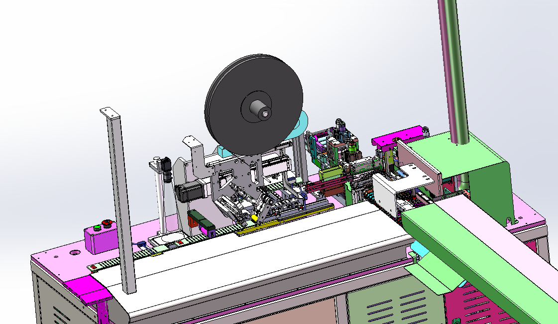
Project Snapshot
- Client Type
- Single-End Sensor Assembly Manufacturer
- Timeline
- Project dated 2026-03-21
- Deliverables
- Wire cutting and board-loading module
- Dual-wire sleeve feeding and inspection module
- Single-end welding head and CCD inspection modules
- Tube-pushing, heat-forming, discharge, bending and pressing modules
Background
Project scope
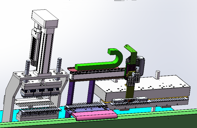
We designed an automated welding and assembly line for electronics sensor single-end wire products. The line links wire cutting and board loading, sleeve assembly and inspection, single-end welding, CCD inspection, tube pushing, heat forming, discharge, bending, shell pressing and collection. That makes the scope an automated assembly solutions application for single-end wire cutting, sleeve assembly, welding, ccd inspection and heat forming.
The confirmed equipment target is 600 to 800 PCS/H with three operators. The utility requirements are 0.5 to 0.7 MPa compressed air and AC220V power. The control architecture is HMI plus PLC.
Challenge
Coordinating wire, sleeve and welding processes
This line has to keep small wire products aligned across several mechanical operations. Wire cutting and board loading define the initial pitch, sleeve feeding adds another component stream, and welding has to occur after the parts are positioned repeatably.
Inspection before downstream forming
The process includes front-side and back-side visual inspection. That inspection needs to happen before tube pushing, heat forming and final pressing, because defects or missing parts should be identified before more value is added downstream.
Changeover impact
The technical notes state that changing the assembled product requires replacing all fixtures and adjusting related components. Incoming material dimensions must stay within the corresponding tolerance range, and the final equipment size is subject to the refined 3D design and actual build.
Approach
Wire boarding and sleeve assembly
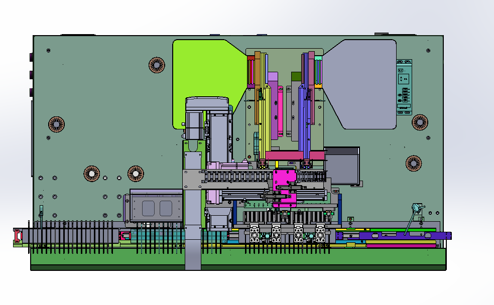
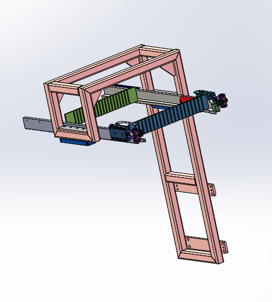
The front end uses a single-wire cutting and board-loading section with a wire-feeding rack, wire straightening, board transfer, tape application and visual inspection. The sleeve section uses sleeve feeding, sleeve transfer tooling and a sleeve mold that handles two sleeves per cycle.
Welding and visual inspection
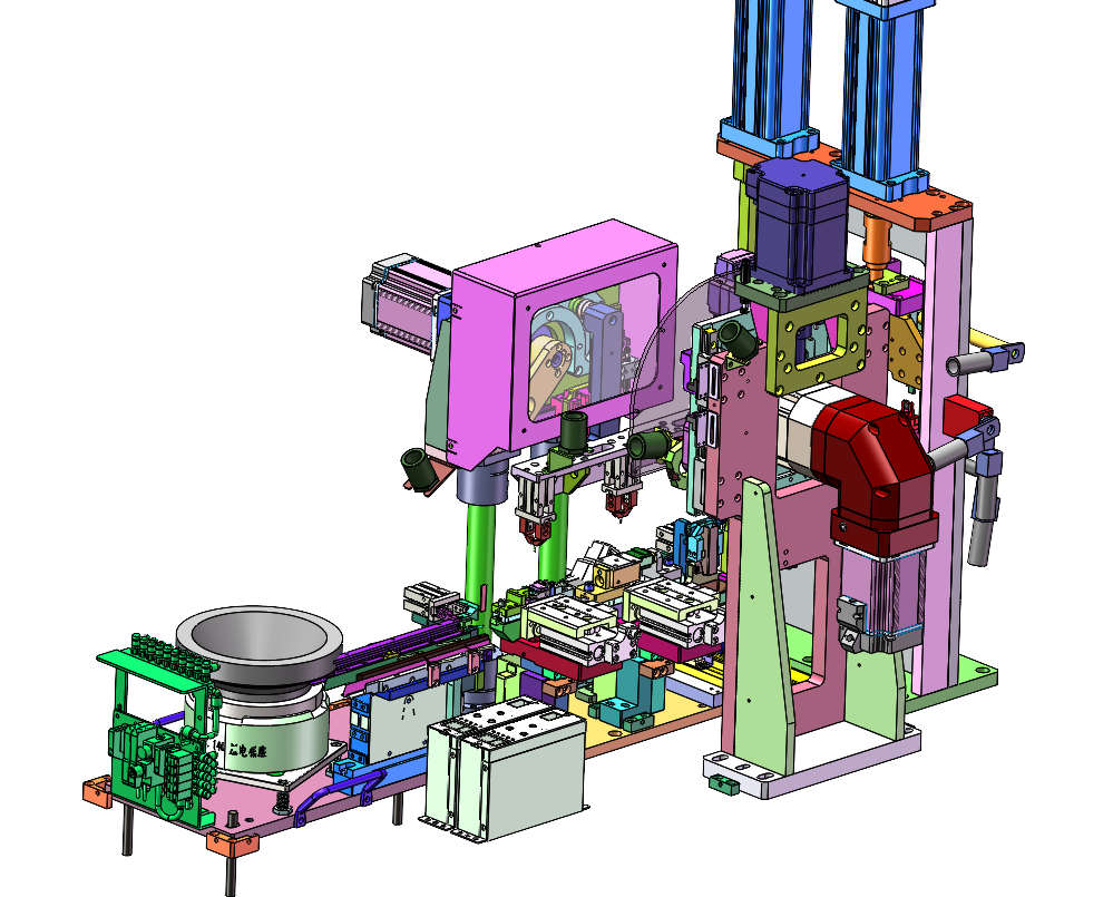
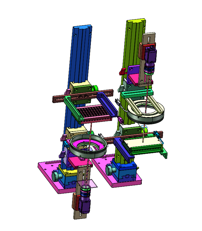
After sleeve handling, the line moves into the single-end welding head section. A vibratory bowl feeding group supplies the small welding-head components, while the welding module positions and joins the component to the wire assembly. The CCD station checks the front and back sides before the product advances to the forming operations.
We describe the same connected sensor assembly route in our electronic sensor assembly line case study, where wire cutting, sleeve handling, welding, CCD inspection and downstream forming are planned as one controlled production flow.
Tube pushing, heat forming and final handling
The downstream section converts the welded assembly with tube pushing and heat-shrink forming. The final handling section discharges the product, performs bending and shell pressing, and then collects the completed parts.
Confirmed technical parameters
| Item | Confirmed specification |
|---|---|
| Reference layout size | Based on actual 3D design; final size to be confirmed after detailed design |
| Working capacity | 600 to 800 PCS/H |
| Required compressed air | 0.5 to 0.7 MPa |
| Required power | AC220V |
| Control system | HMI plus PLC |
| Required operators | 3 |
| Product changeover | Requires replacing all fixtures and adjusting related components |
Outcome
Proposed operating result
The line concept turns a multi-step single-end wire process into one connected automation route. It reduces manual transfer between cutting, sleeve handling, welding, CCD inspection, heat forming and final pressing, while keeping the confirmed operator plan at three people.
Engineering value
By placing CCD inspection before the downstream forming and pressing operations, the design gives the production team a clearer control point before additional process steps are applied. The confirmed capacity, utility and operator values also make the concept concrete enough for mechanical detailing, fixture design and final layout sizing.
Project Feedback
Share a short review of this case study or tell us what kind of automation project you want to compare it with.
No published reviews yet.