
AC/DC Socket Bushing Automatic Assembly Line
Bushing Automatic Assembly Line for AC/DC socket components, combining thermistor forming, housing feeding, resistor assembly, laser welding, testing and tray loading.
See how we designed this project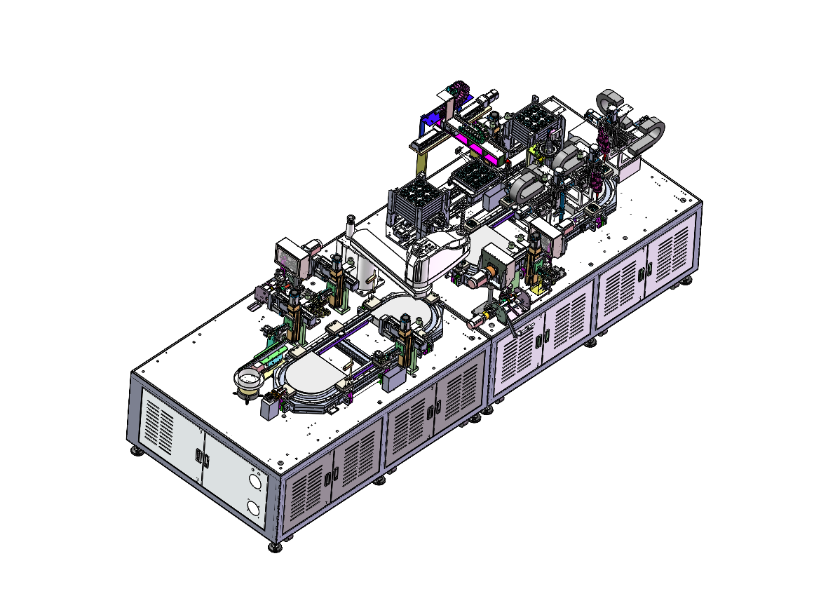
Project Snapshot
- Client Type
- EV Charging Component Manufacturer
- Timeline
- Project dated 2025-09-11
- Deliverables
- Front and rear automatic assembly-line layout
- Dual eight-station magnetic-loop transport plan
- Taped thermistor forming, resistor feeding and plastic-housing loading modules
- Solder-paste dispensing, laser welding, resistance test, CCD inspection and tray handling modules
Background
Project scope
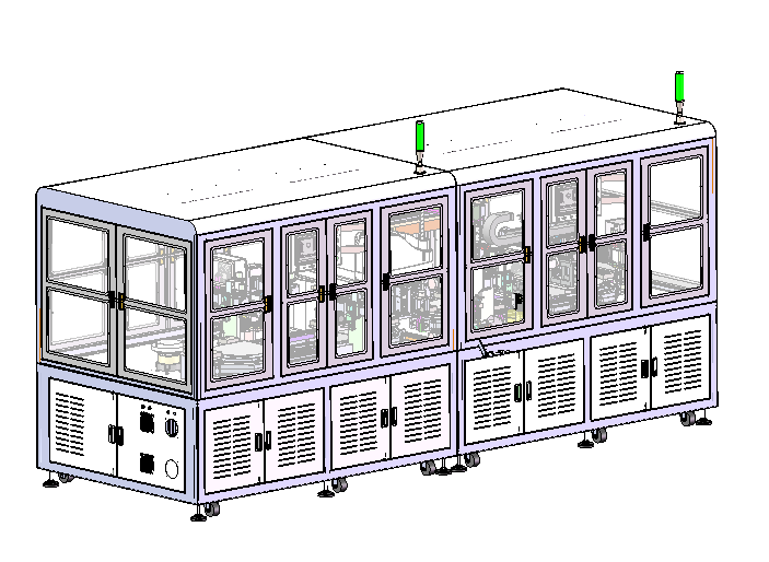
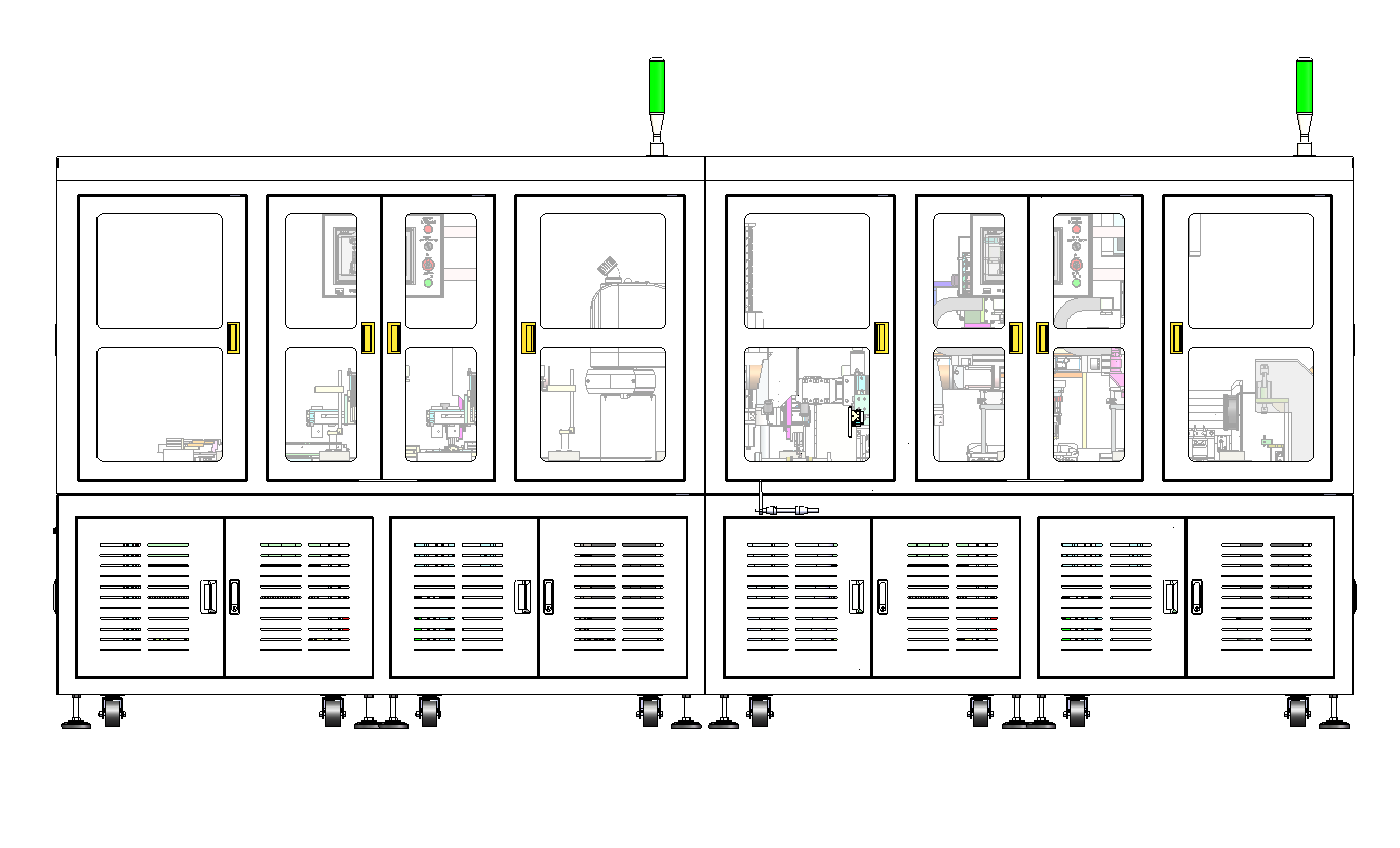
We designed an automatic EV charging power-component assembly line for AC/DC charging-socket bushing assemblies. The line is divided into a front section for resistor, thermistor and plastic-housing assembly, and a rear section for assembly, laser welding, testing and tray unloading. That makes the scope a Bushing Automatic Assembly Line application for socket bushing, thermistor, resistor assembly and laser welding.
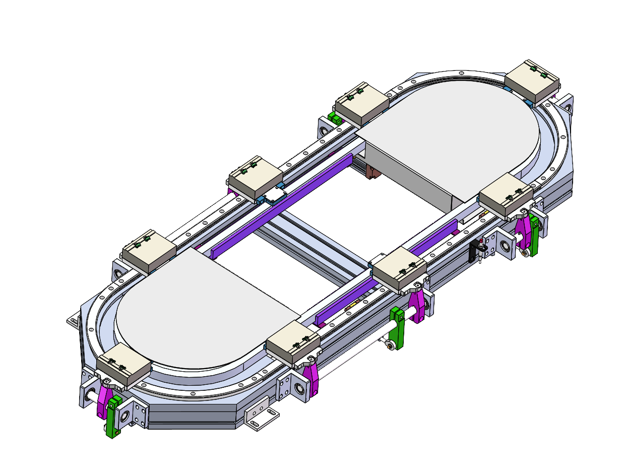
The machine concept uses two eight-station ring-type magnetic levitation transport loops, four-axis robots, two CCD systems, solder-paste dispensing with height detection, two three-axis laser welding modules, resistance testing, CCD appearance inspection, nonstop tray loading and NG removal.
Challenge
Coordinating two product variants
The equipment has to support both DC and AC charging-socket versions. The DC version includes one more resistor than the AC version, so the DC flow uses an additional resistor feeding and transfer mechanism. The AC flow removes that resistor feeding and handling section while keeping the rest of the assembly, welding, testing and tray handling route aligned.
Dedicated fixtures and controlled incoming tolerances
The technical notes define the machine as dedicated-purpose. If the assembled product changes, all fixtures and grippers need to be replaced. Incoming dimensions also need to stay within the corresponding tolerances, so the automation plan depends on controlled part geometry rather than trying to absorb large variation at the machine.
Approach
Module architecture
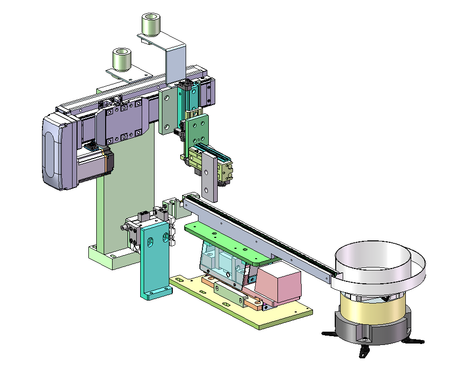
The line is organized around front-end component preparation and rear-end welding/test handling. The front section includes taped thermistor forming and feeding, plastic-housing vibratory feeding, resistor carrying and loading, resistor lead cutting and loading, resistor assembly, assembly-position detection and NG rejection. The rear section includes two three-axis laser welding modules, solder-paste dispensing with laser height measurement, resistance testing with a standard-sample station, CCD weld appearance inspection, nonstop tray loading and a four-axis pickup plus NG rejection module.
Front-end assembly
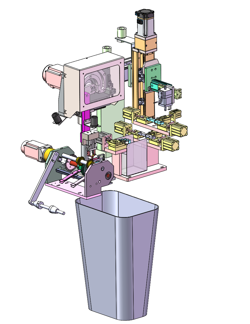
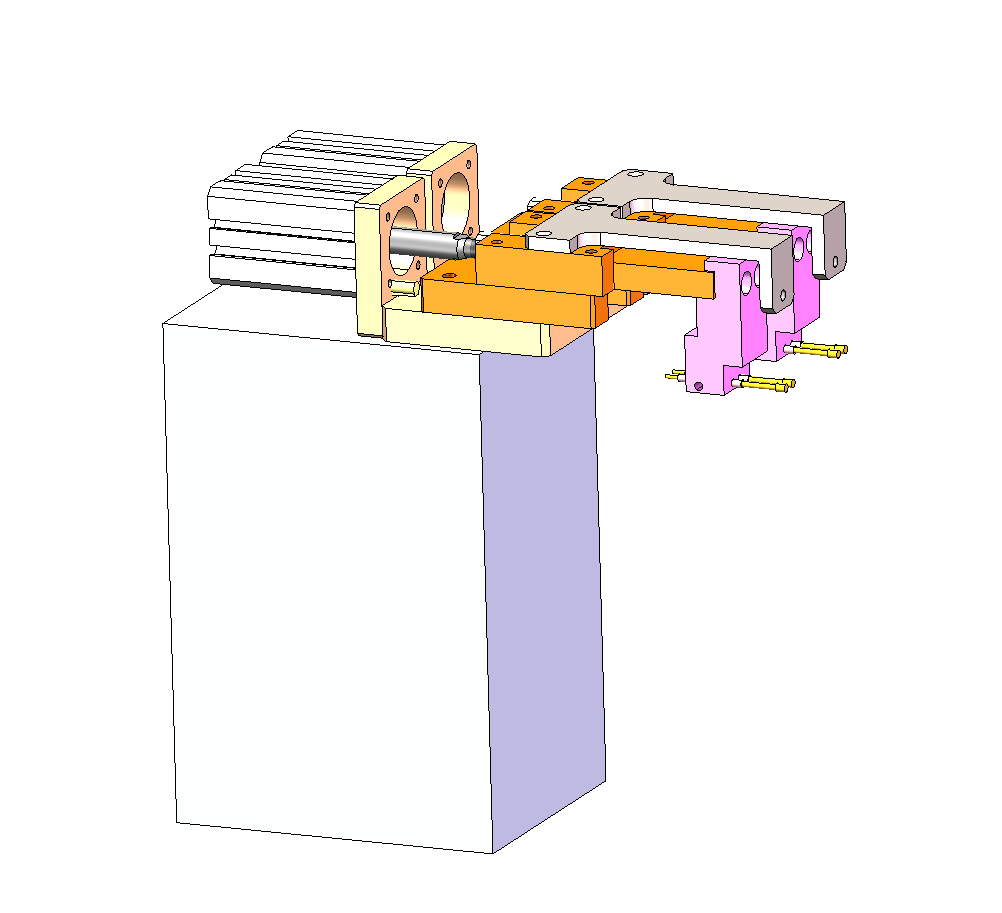
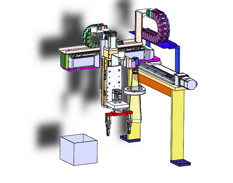
The taped thermistor forming and feeding module includes a tape reel shaft, stepping cut-and-feed unit, lead-cutting mechanism, left/right forming pushers, front pusher, PPU feeding, four-axis pickup, Y-axis transfer and lift/shift slides, plus an NG waste-tape bucket. Plastic housings are fed by vibratory bowl, straight vibration rail and separation module, then picked by a shaped suction nozzle.
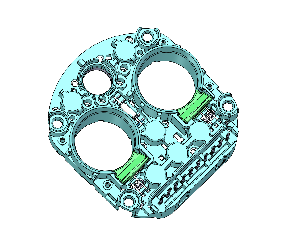
The resistor assembly station uses a material-pushing cylinder, plastic-housing support rod, pin-foot probe and base. The eight-station magnetic-loop section uses moving platforms, ring rails, fixture tables and secondary positioning structures to carry parts through the front assembly route.
Welding, testing and unloading
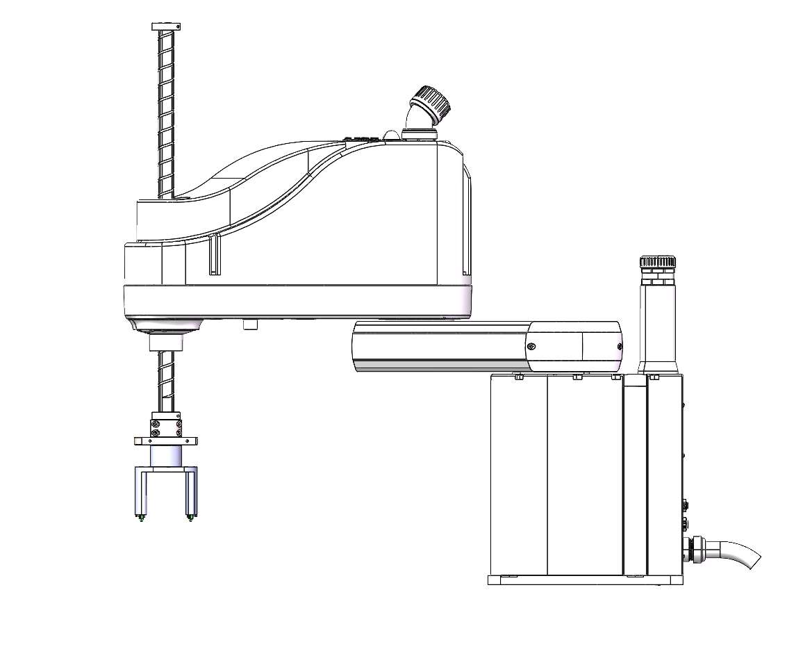
The four-axis assembly robot uses a shaped assembly suction nozzle and pressure sensor. The solder-paste module uses a high-precision three-axis module, solder-paste valve, dispensing needle and laser height sensor. Welding is handled by two three-axis laser welding modules; the validation note lists a 3-second single-point weld and six weld points using two laser systems.
After welding and cooling, the rear section performs resistance testing and CCD appearance inspection. The test module includes appearance-detection CCD, test probes, cooling fan and standard-sample placement table. The tray handling module provides nonstop tray loading and unloading with separate waiting tray warehouse, finished tray warehouse, working bay and lifting component. A four-axis pickup and NG rejection module handles X/Y/Z/R movement, alternating grippers, CCD appearance inspection and NG box placement.
For readers reviewing the complete AC/DC socket route, we also describe the same bushing assembly-line logic in our AC/DC bushing assembly line case study, including how component feeding, laser welding, resistance testing and tray handling are coordinated as one production sequence.
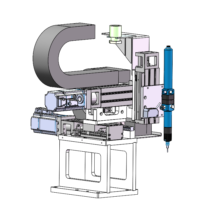
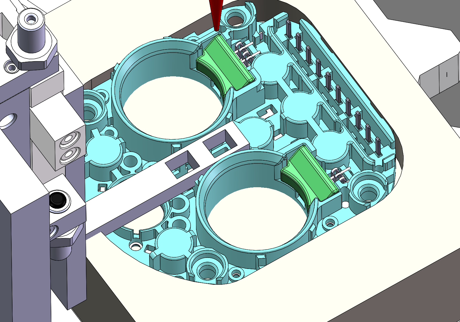
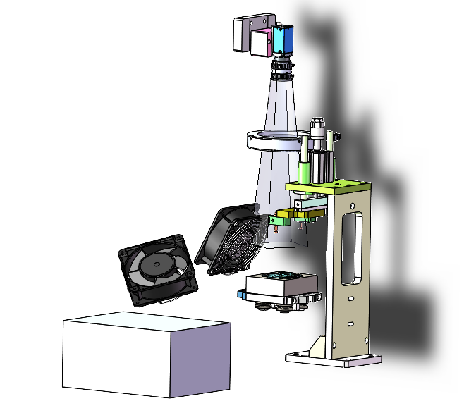
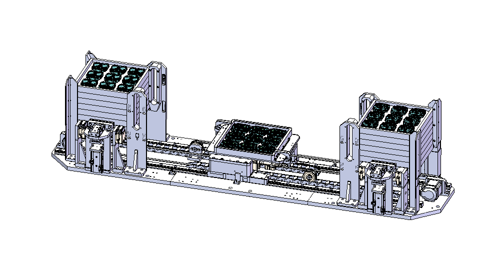
Variant handling and control package
For the DC charging-socket route, the process includes thermistor feeding, plastic-housing feeding, base pickup, push-in assembly, pressure-monitored four-axis installation, solder-paste dispensing with height check, two laser welding stages, cooling, resistance test, CCD inspection, tray output and NG rejection. For the AC route, the main reduction is one resistor and the related resistor feeding/transfer mechanism.
| Item | Confirmed specification |
|---|---|
| Transport | Front and rear eight-station ring-type magnetic levitation loops |
| Inspection | Two CCD systems, with front and rear display/touchscreen interfaces |
| Welding | Two three-axis laser welding modules; validation note lists 3 seconds per single weld point and six weld points |
| Testing | Resistance test with CCD appearance inspection and standard-sample station |
| Tray handling | Nonstop tray loading/unloading with waiting tray and finished tray warehouses |
| Control package | One control system |
| Capacity | Average 300 to 350 products per hour |
| Changeover constraint | Dedicated machine; product changes require replacement of all fixtures and grippers |
Outcome
Proposed operating result
The resulting line gives the production team a detailed automation route for AC/DC socket bushing assembly, from component feeding and forming through laser welding, resistance testing, CCD appearance inspection and tray unloading.
Process value
The value is integration across many small, tolerance-sensitive steps: taped thermistor forming, plastic-housing feeding, resistor handling, fixture-based magnetic-loop transfer, laser welding, test verification and NG removal are all tied into one controlled route. The available project data does not include equipment price, labor saving or payback period, so we do not assign an ROI figure.
Project Feedback
Share a short review of this case study or tell us what kind of automation project you want to compare it with.
No published reviews yet.