
Semi-Automatic Assembly Equipment for Semi-Automatic Inductor Copper-Clip Assembly Cell
Semi-Automatic Assembly Equipment for inductor copper-clip placement, using CCD positioning, linear-motor motion, marble-platform stability and 120-part fixtures.
See how we designed this project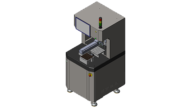
Project Snapshot
- Client Type
- Electronics Manufacturer
- Timeline
- Project dated 2025-04-19
- Deliverables
- Semi-automatic copper-clip assembly process
- CCD vision positioning for inductor and copper clip
- Fixture and curing-cycle sizing
- Precision and tolerance risk review
Background
Project scope
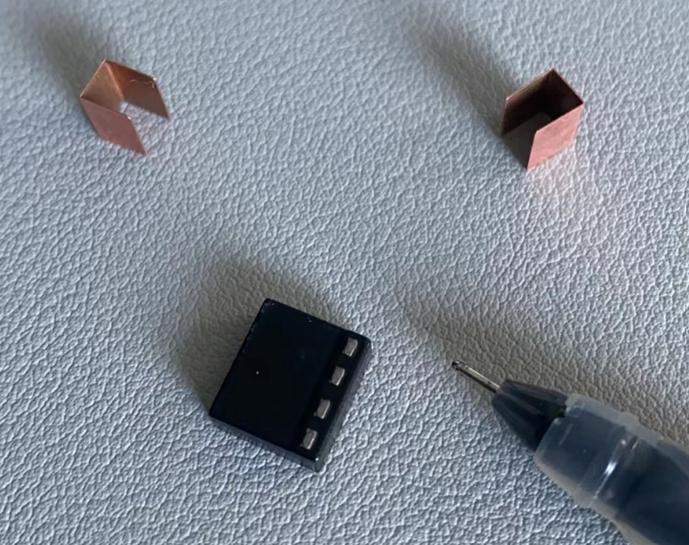
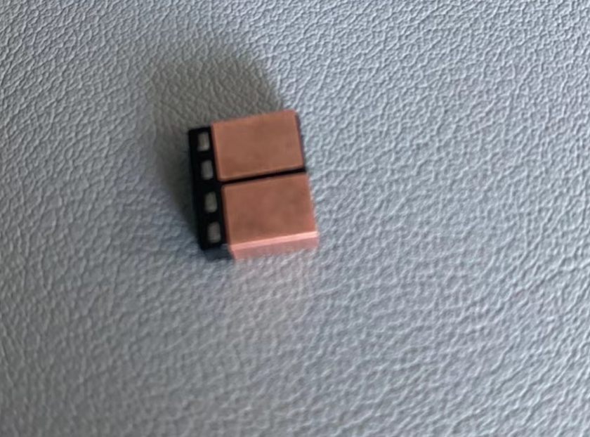
We designed a semi-automatic electronics component assembly cell for placing glued copper clips onto inductors. The target assembly accuracy is +/-0.03 mm. The product requirement also notes that the copper piece must not show outward splay or warpage after assembly. That makes the scope a Semi-Automatic Assembly Equipment application for inductor copper-clip placement and curing.
The process is intentionally semi-automatic: operators load inductors into fixtures and load pre-dispensed copper-clip fixtures, while the machine handles vision positioning, pickup, placement and fixture-level transfer.
Challenge
Accuracy on dark parts
The requirement calls out that CCD recognition and positioning on black inductors is difficult. That creates a practical risk for assembly repeatability because copper-clip placement depends on both inductor recognition and copper-clip recognition.
Copper-clip tolerance stack
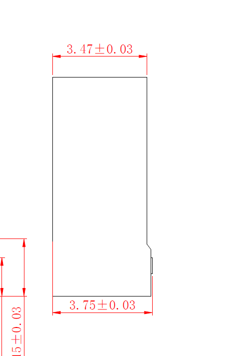
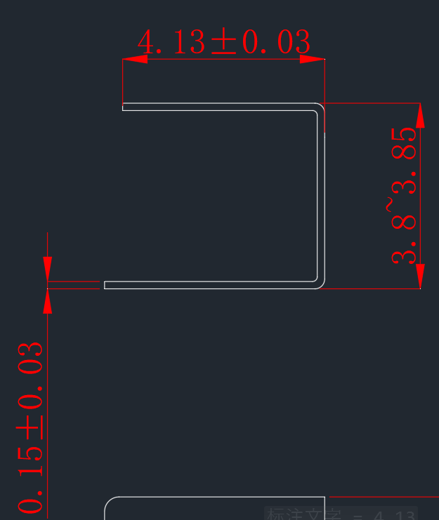
The copper clip has a 90 deg +/-0.3 deg opening-angle control requirement. The tolerance discussion also lists inner-opening, thickness and one-side angle tolerances, with a minimum inner opening of 3.46 mm and a maximum of 3.59 mm before thickness tolerance. We treated this as a tolerance-stack risk rather than only a machine-motion problem.
Approach
Machine architecture
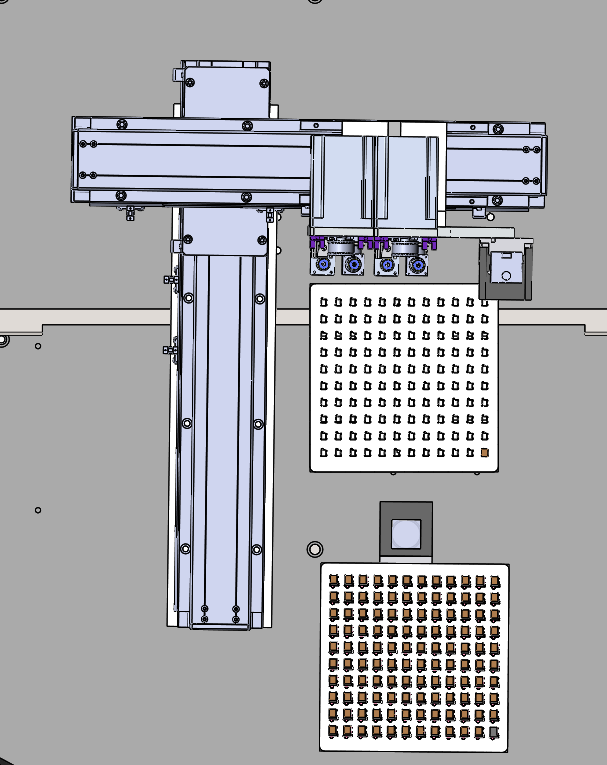
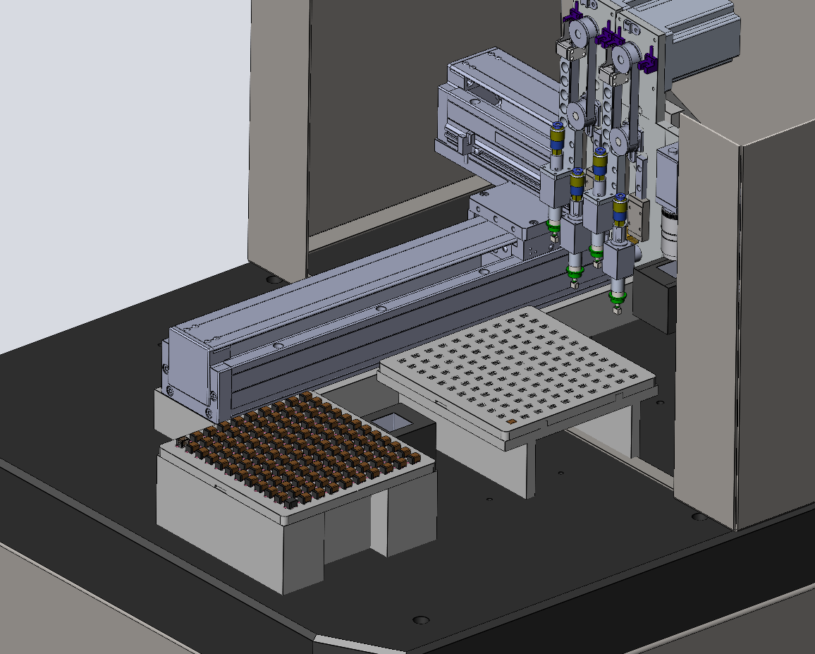
The machine uses tray-style loading and unloading, CCD vision-camera positioning, linear-motor motion, a marble platform for precision stability and PLC integrated control coordinated with the vision system.
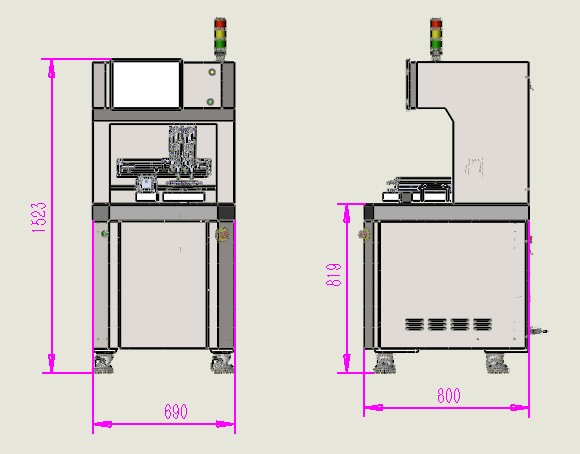
The equipment reference dimensions are W700 x D800 x H1530 mm, with an 820 mm working height. The utility requirements are 220 V 50 Hz power, 3.5 kW power rating and 0.4 to 0.7 MPa air supply.
For a related Robotlyne semi-automatic assembly application, see our home appliances semi-automatic assembly equipment case study: https://www.robotlyne.com/home-appliances-semi-automatic-assembly-equipment-case-study/
Process flow
The process sequence is:
- Place inductors into the fixture.
- Place the glued copper-clip fixture.
- Pick the copper clip.
- Assemble one-side copper clip onto the inductor.
- Bake and cure the assembly.
- Remove products manually and re-tray them for the next-side process.
The concept note states that this machine assembles one copper clip side. Two-sided finished products therefore repeat the process after manual removal, tray placement and curing.
Fixture and takt planning
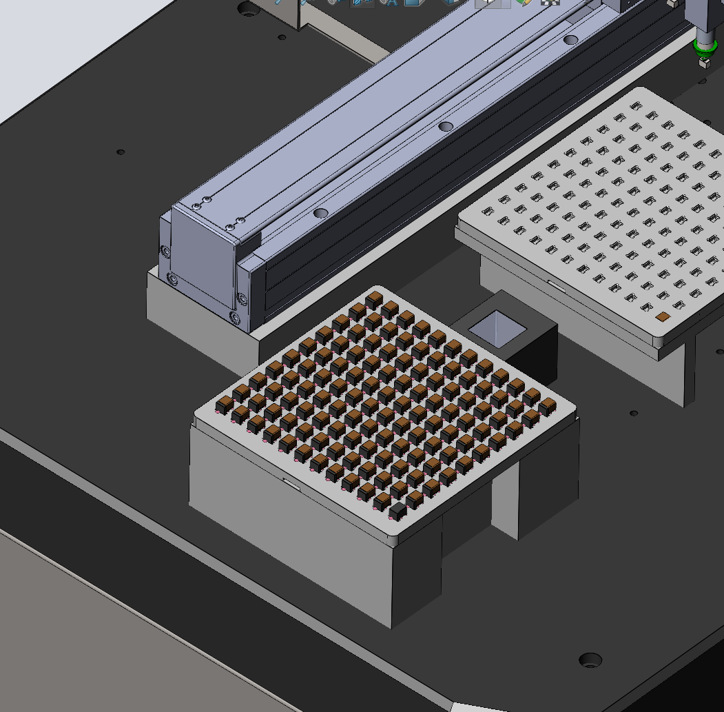
Each fixture holds 120 products. The plan estimates 4 minutes to fill 120 products, 1 minute for loading/unloading and 5 minutes per assembly cycle before baking. Baking is estimated at 30 minutes, cooling at 3 minutes and product removal at 2 minutes. From the 35-minute bake-to-removal cycle and 5-minute machine cycle, the theoretical fixture requirement is 7 fixtures. We recommend 8 fixtures after adding a 25% reserve.
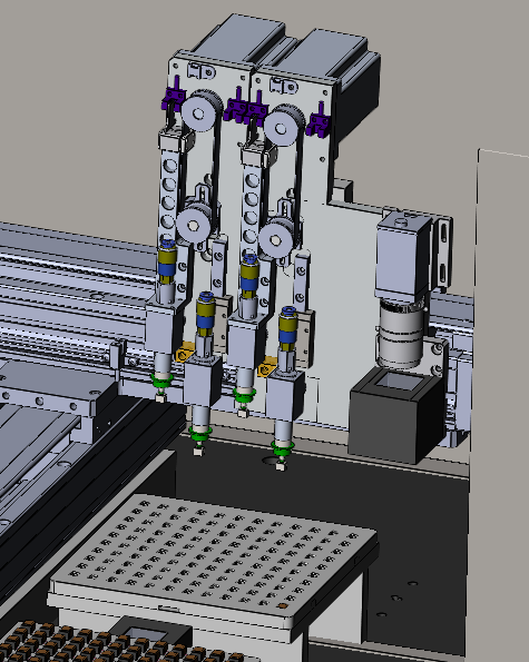
Precision stack
| Accuracy item | Planning value |
|---|---|
| XY manipulator positioning | +/-0.005 mm |
| Rotary positioning | +/-0.01 mm |
| Vision positioning | +/-0.005 mm |
| Equipment installation accuracy | +/-0.005 mm |
| Environmental influence | +/-0.002 mm |
| Theoretical dual-vision accuracy | +/-0.032 mm |
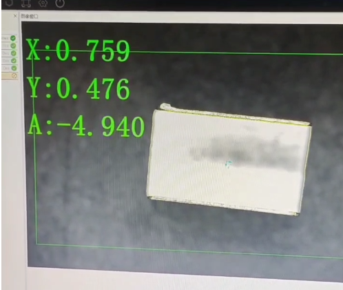
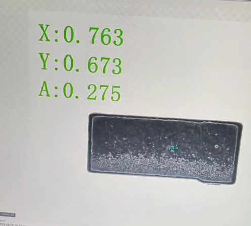
Outcome
Proposed operating result
The cell is designed for about 1,800 to 2,000 pieces per hour for one copper-clip semi-finished side, or about 900 to 1,000 finished pieces per hour after accounting for two-sided assembly. It combines manual fixture handling with high-precision machine placement, which is a more realistic approach than claiming a fully unmanned process for this tolerance condition.
Engineering value
The final plan gives production teams a controlled path for copper-clip placement: fixture-based product holding, dual visual recognition, linear-motor motion, a marble reference platform, defined curing-cycle fixture sizing and an explicit review of copper-clip tolerance risk before build.
Project Feedback
Share a short review of this case study or tell us what kind of automation project you want to compare it with.
No published reviews yet.