
Lead Forming and Feeding Machine for Film Capacitor Lead-Trimming Machine Feeder Improvement
Lead Forming and Feeding Machine retrofit for film capacitors, adding material sensing, an extended hopper, anti-flip pressing, tray fixation and bowl control.
See how we designed this project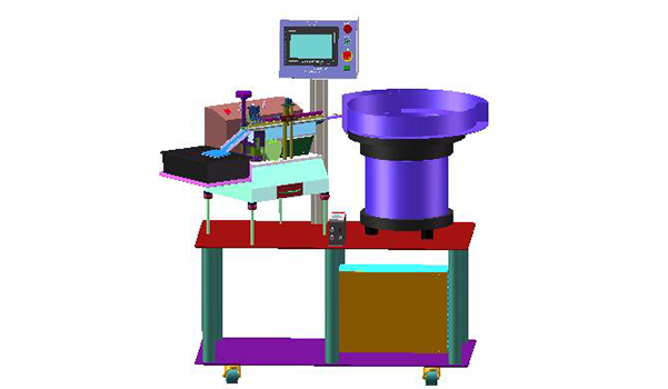
Project Snapshot
- Client Type
- Electronics Manufacturer
- Timeline
- Project dated 2025-06-12
- Deliverables
- Optical fiber full-material and shortage detection
- Extended receiving hopper and buffer area
- Receiving tray fixed bracket
- Vibratory bowl timing and electrical-control upgrade
Background
Project scope
We prepared an electronics capacitor improvement package for an existing film-capacitor lead-trimming machine. The work focuses on feeder reliability, material receiving stability and control logic around the vibratory bowl rather than replacing the whole machine. That makes the scope a Lead Forming and Feeding Machine application for capacitor lead trimming and feeder reliability improvement.
The improvement scope includes optical fiber detection for vibratory bowl full-material status, optical fiber detection for direct-vibration material shortage, an extended receiving hopper and a fixed receiving-tray structure.
Challenge
Feeding stability
The existing machine needed better control of incoming material status. We identified two conditions that should be detected automatically: shortage at the direct-vibration feed and full-material status at the downstream area. Without these signals, the vibratory bowl start/stop action is harder to control consistently.
Receiving and anti-flip control
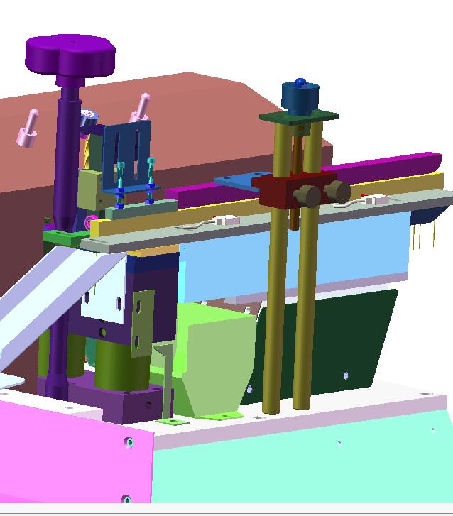
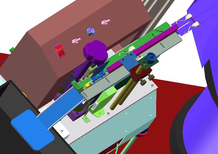
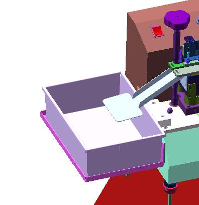
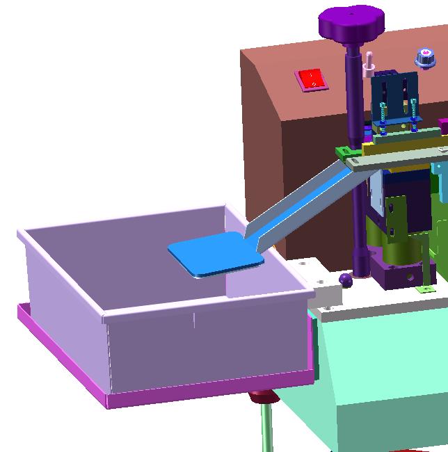
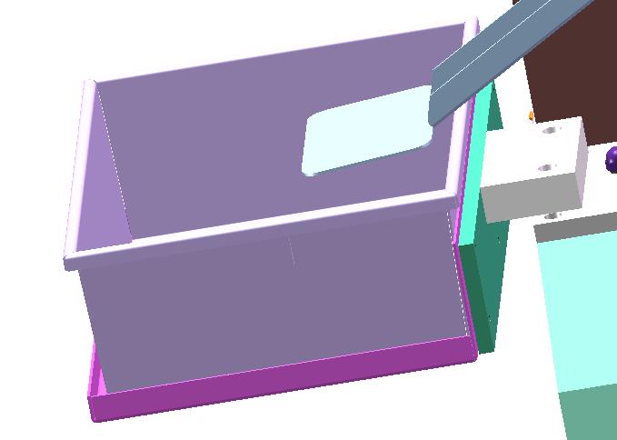
The receiving area also needed mechanical improvement. The plan adds a longer receiving hopper, a buffer zone for falling material, anti-static lining, a receiving tray fixed bracket and an anti-flip pressing block so that parts do not turn over or move unpredictably after trimming.
Approach
Detection and timing logic
We configured two optical fiber sensing functions:
- If the shortage-detection fiber sees no material for 2 seconds, the vibratory bowl starts feeding.
- If the full-material fiber senses material for 2 seconds, the vibratory bowl stops feeding.
The added touch screen is used because vibratory bowl start and stop actions require time-parameter settings rather than fixed manual switching.
For a related Robotlyne electronics lead forming and feeding application, see our electronics lead forming and feeding machine case study: https://www.robotlyne.com/electronics-lead-forming-and-feeding-machine-case-study/
Added mechanical and control parts
| Improvement area | Confirmed addition |
|---|---|
| Material status detection | Two groups of full-material and shortage optical fibers |
| Receiving stability | Extended receiving hopper and buffer area |
| Part orientation | Anti-flip pressing block |
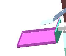
| Tray handling | Receiving tray fixed bracket |
| Vibratory bowl control | Frequency controller |
| Electrical control | Electrical box for optical fiber 24 V power, vibratory bowl start/stop relays and PLC control-board placement |
Outcome
Proposed operating result
The retrofit turns a manually sensitive feeding and receiving area into a controlled machine section with material-status sensing, timed vibratory bowl start/stop logic and a more stable receiving structure.
Improvement package
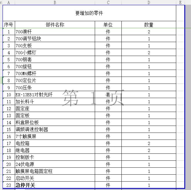
The confirmed part package includes optical fibers, an extended receiving hopper, anti-flip pressing, a receiving tray fixed bracket, a vibratory bowl frequency controller, touch screen, 24 V control power and relay/PLC placement for the added controls.
Project Feedback
Share a short review of this case study or tell us what kind of automation project you want to compare it with.
No published reviews yet.