
Automated Assembly Equipment for Automatic Wire-Board Loading Cell with Vision-Guided Pick and Place
Automated assembly equipment for electronics sensor wire-board loading, using magazine feeding, CCD-guided pickup, tape application, alignment and discharge.
See how we designed this project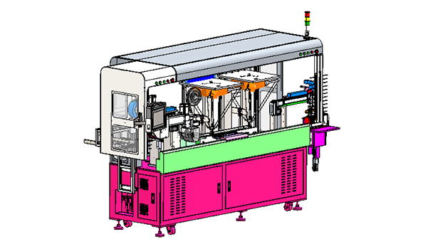
Project Snapshot
- Client Type
- Wire Harness and Sensor Manufacturer
- Timeline
- Project dated 2025-06-13
- Deliverables
- Automatic board-feeding and wire-harness feeding modules
- Dual spider-robot pickup with CCD guidance
- Tape application and wire alignment modules
- Finished-board discharge and NG return flow
Background
Project scope
We designed an automatic electronics sensor wire-board loading cell that lets operators feed empty wire boards and wire harnesses into separate magazines, then uses automated handling, vision-guided pickup, tape application, alignment and discharge to complete the board arrangement process. That makes the scope an automated assembly equipment application for wire-board loading and harness arrangement.
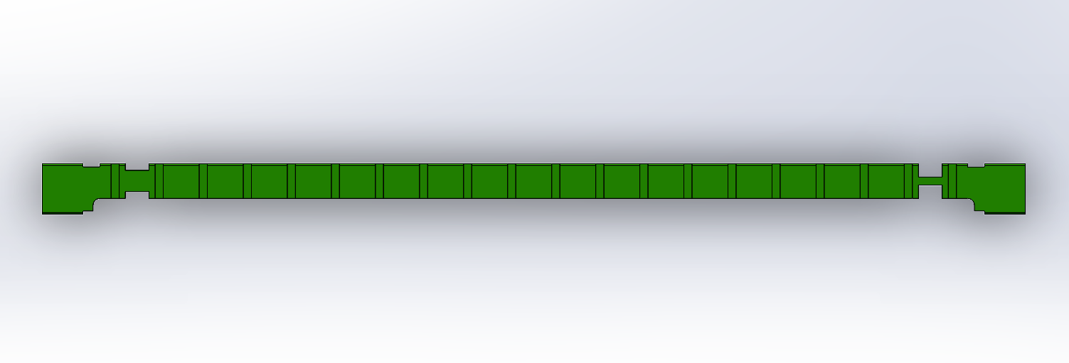
The machine is built as a dedicated solution for one board layout rather than a universal platform. The technical requirement defines a 13 mm board-center interval, and the test product description states that each wire board can hold 40 wire harnesses, with every 2 pieces placed into one slot.
Challenge
Coordinating board and harness feeding
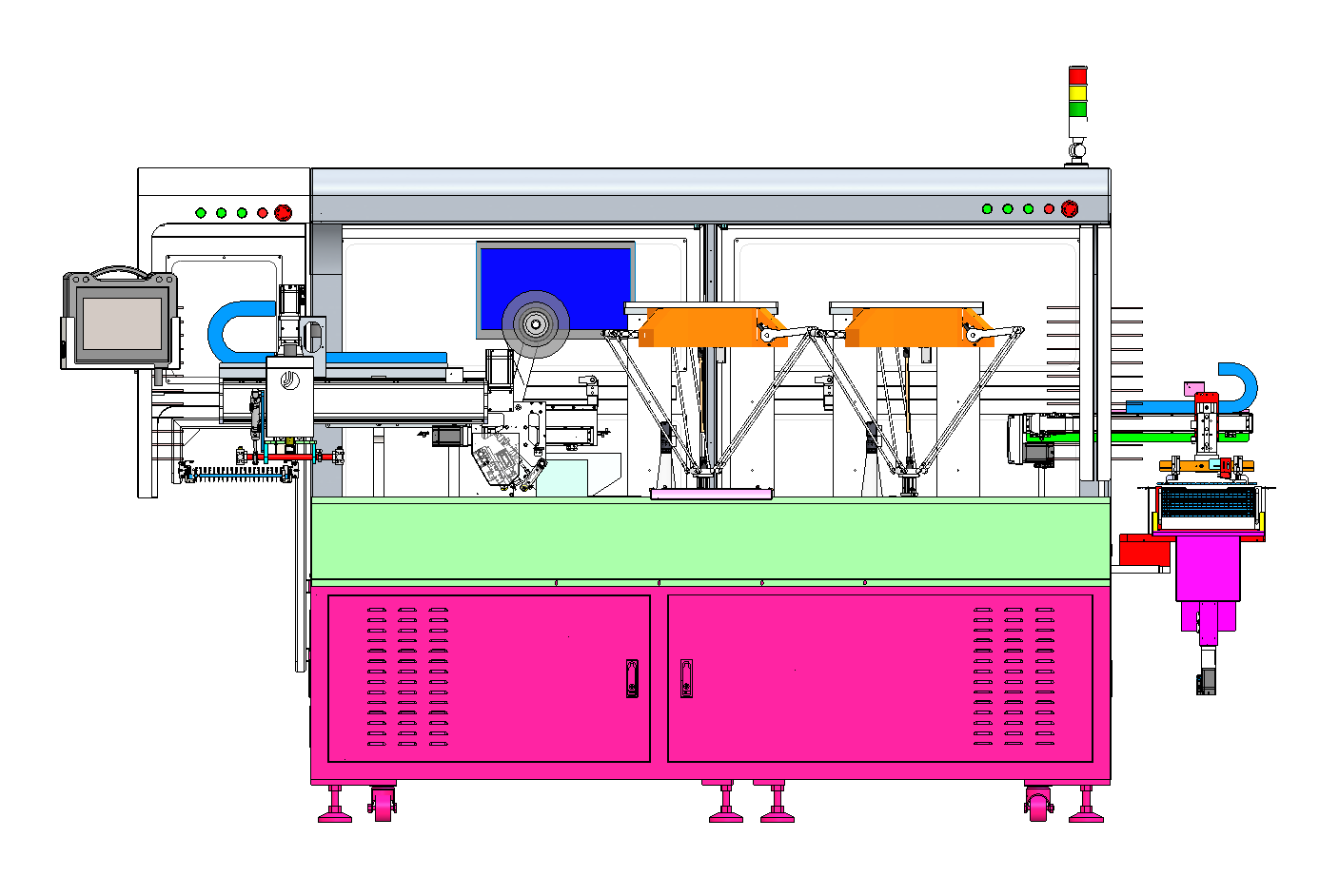
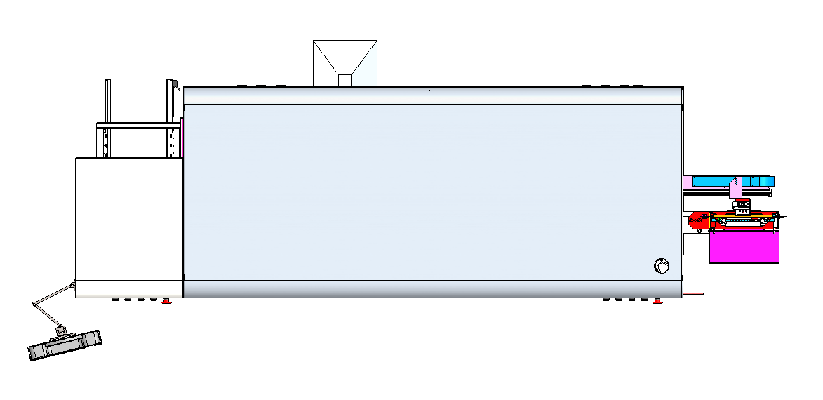
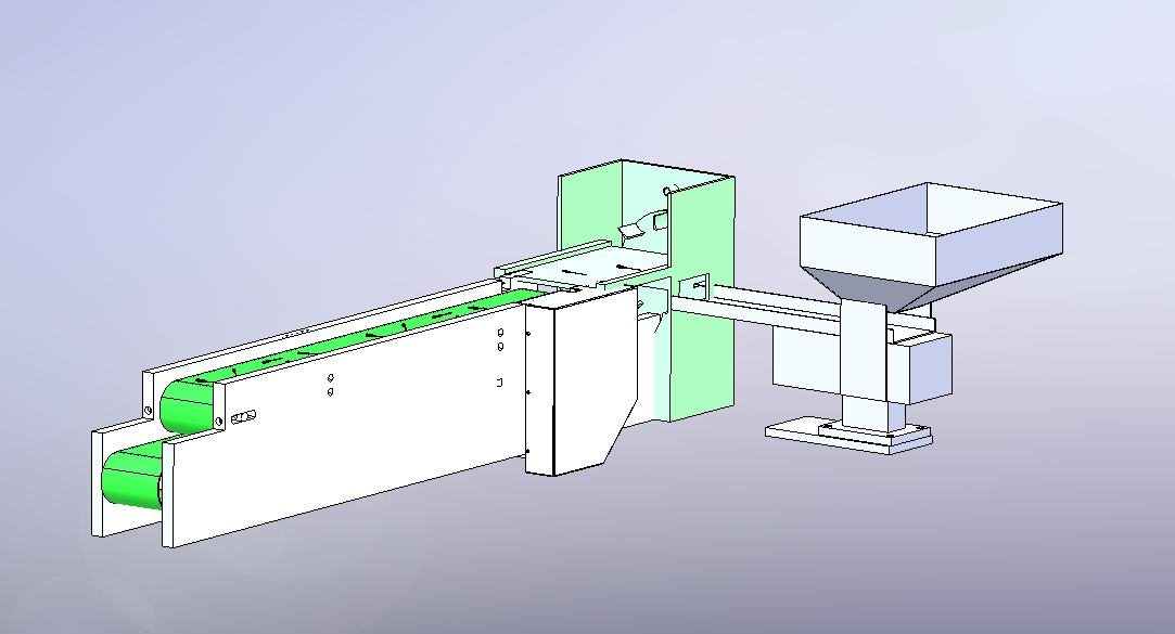
The cell has to synchronize two material streams: empty wire boards and loose wire harnesses. The board side needs magazine feeding, board pickup, transfer into the receiving assembly and later discharge. The harness side needs rotary feeding, vibration-assisted feeding and a two-layer belt path with return capability.
Vision-guided placement and NG handling
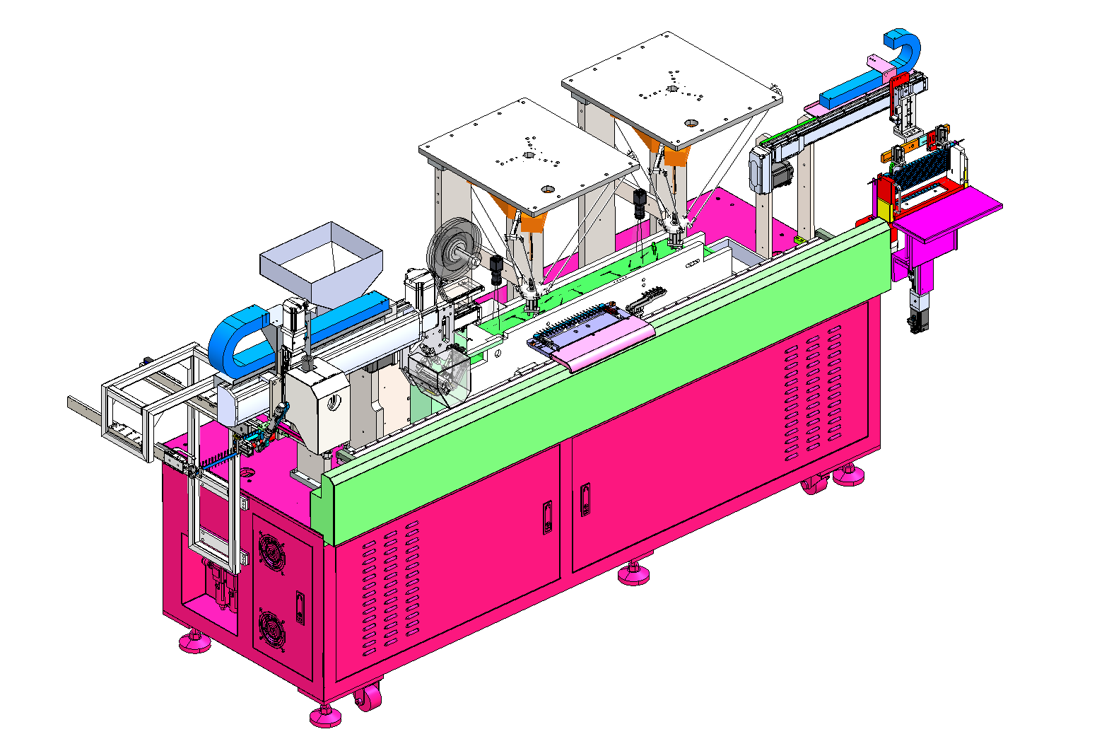
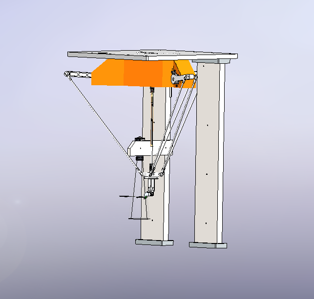
The process depends on wire-harness orientation. If the harness posture is not suitable for placement, the flow sends it through a lower return line and periodically into an NG box. The spider-robot section therefore has to combine CCD guidance, wire gripping and placement stability rather than only basic transfer.
Approach
Main machine modules
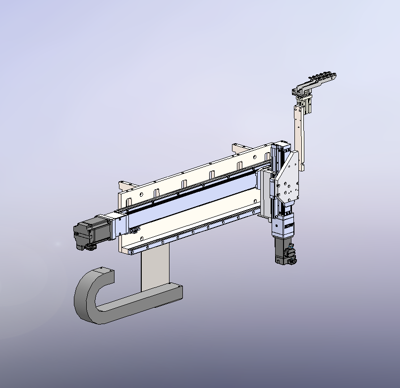
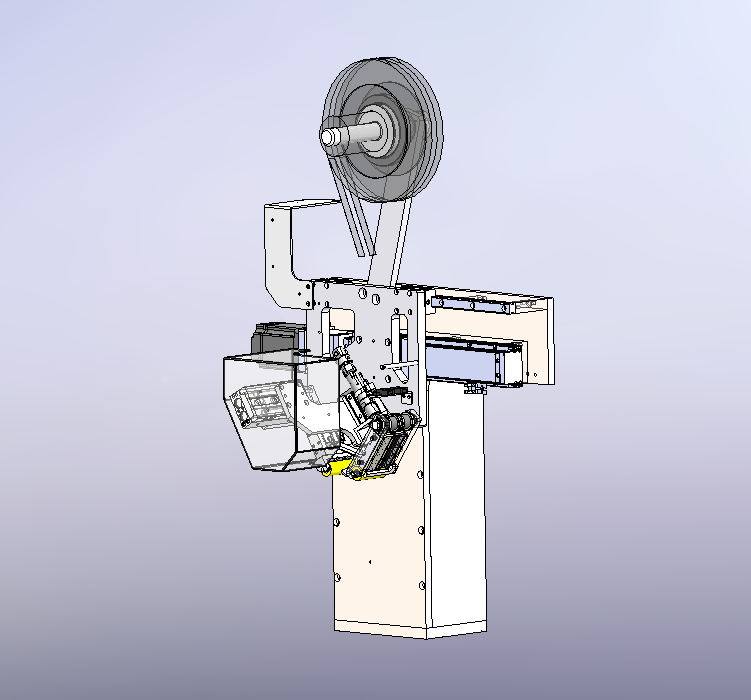
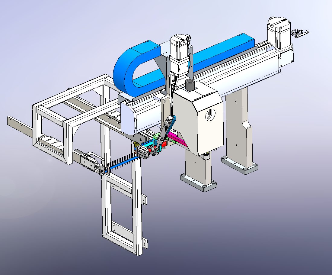
We organized the machine around automatic board loading, automatic wire-harness loading, dual spider-robot pick-and-place, board receiving, wire alignment, tape application and arrangement discharge. The equipment package includes one control system, one display and one touch screen.
For a related automated assembly equipment example, we also discuss this board-loading and harness-arrangement logic in our automated assembly equipment case study, where material feeding, vision-guided pickup, tape application and discharge are coordinated as one cell.
| Module | Confirmed function |
|---|---|
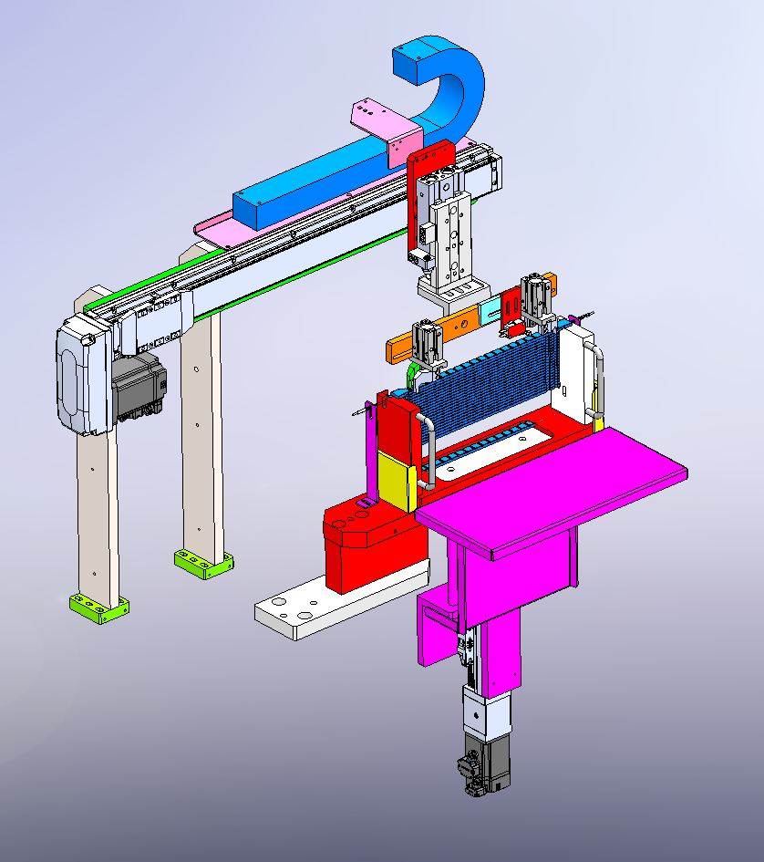
| Automatic board-feeding module | Uses a board magazine, pickup gripper, lift slide cylinder, transverse module, ejector module and through-beam fiber detection |
| Automatic wire-harness feeding module | Uses rotary feeding, a vibration feeder, refill magazine, upper flat feeding belt, lower return belt and belt motor |
| Spider-robot module | Uses two spider robots with CCD vision and wire-gripping pneumatic claws |
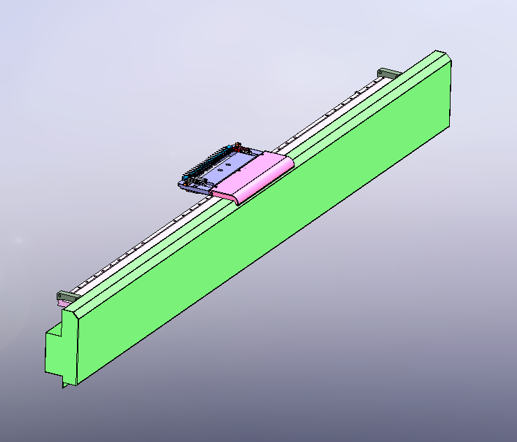
| Board receiving module | Uses a linear-motor module, clamping cylinder, receiving tray and guard plate |
| Wire-aligning module | Uses aligning grippers, transverse movement, lift module, drag chain and linear guide |
| Tape application module | Uses tape, pressing cylinder, scissors and transverse movement |
| Discharge module | Uses a receiving frame, lift module, board-clamping pneumatic claw, turnover cylinder, transverse module and drag chain |
Operating sequence
The station action flow starts with manual loading of the wire board and wire harness into magazines. The module moves laterally, descends and grips the board, places the board into the receiving assembly and sends the harness through rotary feeding to the upper flat belt. CCD guidance supports spider-robot pickup. After placement, the process applies tape, flips and arranges the work, places it into the wire-aligning fixture gripper, and then discharges the finished board for manual removal.
Outcome
Proposed operating result
The resulting cell replaces repeated manual board arrangement with a dedicated automatic process for one board specification. The stated average efficiency target is 1,800 to 2,000 products per hour.
Product and layout constraints
The test product setup is based on boards with 40 wire harness positions. Every 2 pieces share one slot, and the center interval is 13 mm. Because the technical requirement defines the cell as dedicated-purpose, we treated compatibility as intentionally limited rather than adding unsupported multi-product claims.
Project Feedback
Share a short review of this case study or tell us what kind of automation project you want to compare it with.
No published reviews yet.