
Unmanned Workshop AGV Machine-Tending Layout
AGV Machine Tending layout for an unmanned workshop, covering CNC loading, cleaning, hole inspection, tray loading and AGV composite robot transfer.
See how we designed this project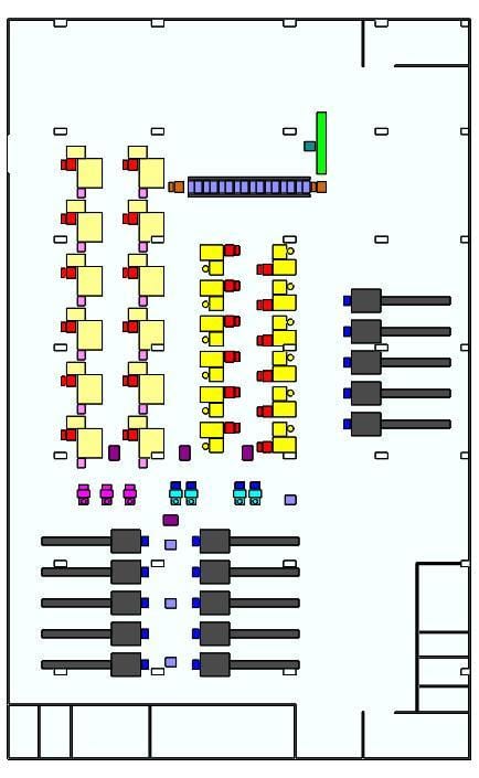
Project Snapshot
- Client Type
- Precision Machining Plant
- Timeline
- Project plan dated 2026-04
- Deliverables
- Overall unmanned workshop layout
- Composite robot station quantity plan
- CNC, cleaning, inspection and tray-loading process map
- AGV transfer concept for machine-side material flow
Background
Project scope
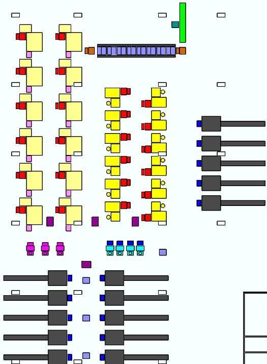
We developed a workshop-level automation concept for unmanned loading and material transfer. The design covers CNC lathes, cleaning machines, hole inspection machines, tray loading machines, AGV composite robots and line-side production equipment. That makes the scope an AGV Machine Tending application for unmanned workshop material loading.
The equipment list includes 15 CNC lathes and infeed ports, 4 cleaning machines, 4 hole inspection machines, 3 tray loading machines, 6 to 7 AGV composite robots, 12 vibrating-bowl feeding machines for downstream processing, 24 discharge modification and tray-loading positions, 12 tray-feed processing machines, 8 cleaning-machine pick-and-place modules, one flat belt line and one AOI inspection machine.
Challenge
Whole-workshop coordination
The project is not a single workstation. It requires CNC loading, cleaning, inspection, downstream processing, tray handling and AGV movement to be laid out as one production area. The key challenge is to place composite robot stations where they can serve equipment without blocking operator access, machine maintenance or AGV routes.
Process density
The plan combines many equipment types in one workshop. CNC lathe loading, cleaning, hole inspection, tray loading and downstream feeding each have different cycle and access requirements. A practical layout must keep short transfer paths while preserving enough space for fixtures, trays and robot motion.
Approach
Production flow
The design maps raw material into CNC lathes, then through cleaning, hole inspection, downstream processing and tray loading. AGV composite robots connect these stages and reduce direct manual feeding between machine groups.
Equipment planning
The layout uses the confirmed equipment quantity basis from the project brief:
| Area | Confirmed quantity basis |
|---|---|
| CNC lathe and infeed ports | 15 |
| Cleaning machines | 4 |
| Hole inspection machines | 4 |
| Tray loading machines | 3 |
| AGV composite robots | 6 to 7 |
| Vibratory-bowl feeding machines | 12 |
| Discharge modification and tray-loading positions | 24 |
| Tray-feed processing machines | 12 |
| Cleaning-machine pick-and-place modules | 8 sets |
| AOI inspection machine | 1 |
Layout method
We use the equipment quantity and process sequence to reserve robot work envelopes, transfer points and AGV paths. The layout treats the AGV composite robots as shared service equipment rather than isolated machines, so robot quantity and station positions are planned at workshop level.
For a fuller walkthrough of how we treated the composite robots as shared machine-tending resources across CNC loading, cleaning, inspection and tray loading, see our shared composite robot machine-tending layout article.
Outcome
Expected value
The solution creates a structured unmanned-workshop plan instead of a set of independent automation islands. It gives the machining area a clearer route from raw-material loading through CNC, cleaning, inspection, downstream processing and tray handling.
Implementation basis
The case uses only confirmed project information for equipment quantities and process coverage. Where drawing dimensions were unreadable in the working files, we retained the layout intent and avoided publishing uncertain dimensional values.
Project Feedback
Share a short review of this case study or tell us what kind of automation project you want to compare it with.
No published reviews yet.