
Inquiries, partnerships, and case study downloads:sales@robotlyne.com
Automated Assembly Line for Automotive Drive Motor Temperature Sensor Automation Line
Automated assembly line concept for automotive drive-motor temperature sensors, covering wire cutting, NTC welding, coating, curing, crimping and testing.
Project Snapshot
- Client Type
- Automotive Sensor Manufacturer
- Timeline
- Project dated 2026-07-23
- Deliverables
- Wire cutting, stripping, tinning and board-loading machine
- Dual-station NTC resistance welding and optional AI CCD inspection
- Silicone coating, tunnel curing and epoxy dispensing modules
- Terminal crimping, connector assembly and performance-test planning
Background
Project scope
We planned an automation route for automotive drive-motor temperature sensor manufacturing. The scope connects wire cutting and stripping, wire tinning and board loading, NTC thermistor resistance welding, automatic silicone coating, drying and curing, shell assembly, epoxy resin injection, second curing, terminal crimping, sleeving, connector assembly, performance inspection, appearance inspection and packaging. That makes the scope an automated assembly line application for wire cutting, boarding, resistance welding, silicone coating, curing, shell assembly, epoxy dispensing, terminal crimping and performance testing.
The project is not a single-machine replacement. It defines a staged line concept that converts the front-end wire and thermistor process into a linked automation route, while leaving selected downstream assembly and inspection operations as manual or semi-automatic where the planning data does not confirm full automation.
Challenge
Balancing automated and manual operations
The full manufacturing route includes automatic, semi-automatic and manual operations. Wire cutting and stripping can be automated, terminal crimping is semi-automatic, while several assembly and inspection stages remain manual in the confirmed process map. The line therefore has to improve the bottleneck steps without pretending that every downstream task is already fully automated.
Board and fixture turnover
The wire boarding stage uses process boards to carry products through welding and downstream handling. For a 10-hour production day, the plan calculates at least 1,000 wire boards for the active working requirement and recommends another 1,000 boards based on a one-day return-cycle assumption.
Quality checks before value-added steps
The welding stage can be followed by optional AI CCD inspection. This is important because the later silicone coating, curing, shell assembly and dispensing stages add process value after welding. The concept places inspection before these downstream operations so NG parts can be rejected earlier.
Approach
Wire cutting, stripping, tinning and board loading
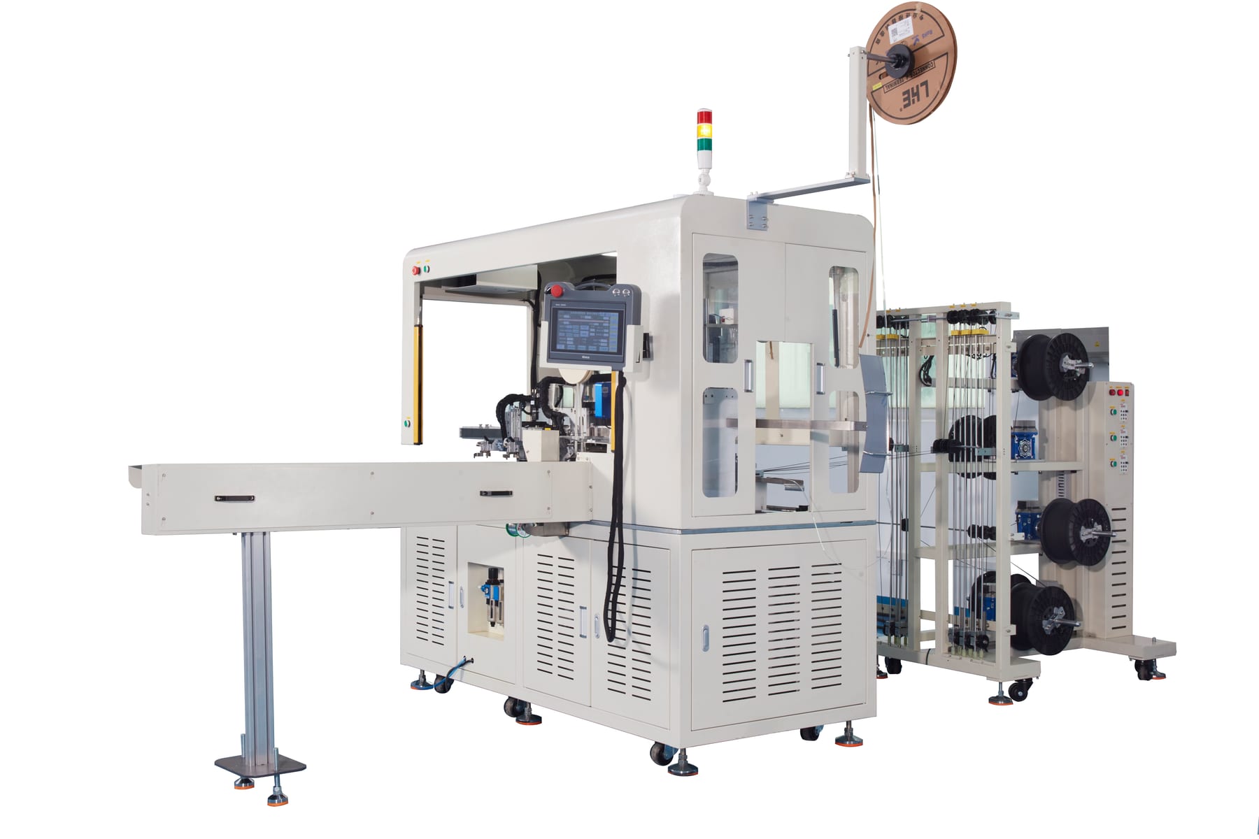
The front-end machine uses five wire-feeding reels and supports a confirmed wire-length range of 50 to 1,500 mm. The action flow is automatic wire feeding, cutting, stripping, flux application, tinning, board loading, tape application, CCD visual checking and finished board discharge.
The confirmed equipment efficiency is 2,000 to 2,200 PCS/H depending on wire length. At 10 working hours per day, this stage is planned for 20,000 to 22,000 pieces. One machine can reduce one operator for cutting and material transfer plus one operator for tape application, for a stated reduction of two people.
NTC resistance welding and optional CCD inspection
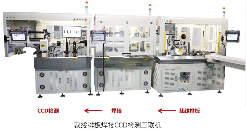
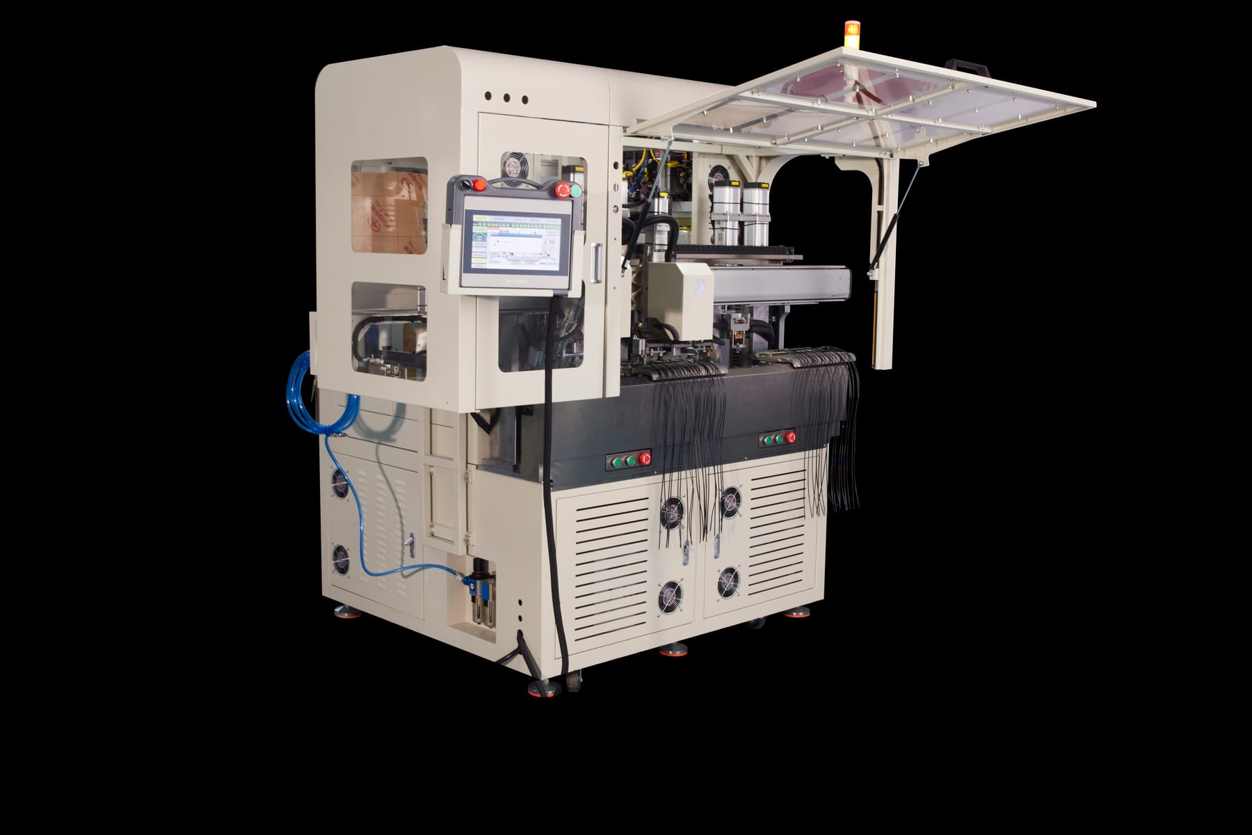
The welding stage positions wires by using the wire board. It uses a dual-station welding concept with confirmed efficiency of 1,600 to 2,000 PCS/H. At 10 working hours per day, one welding machine is listed as sufficient for a 20,000-piece planning level, when linked with the front-end boarding machine and watched together by one operator.
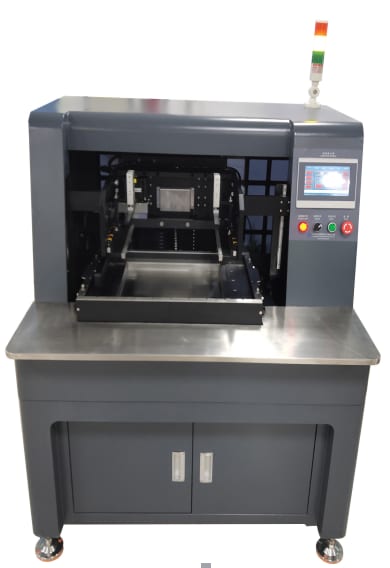
The optional CCD inspection stage checks welded products on the wire board. The confirmed CCD efficiency is 1,800 to 2,400 PCS/H, with the linked rhythm aligned to the front-end boarding stage. The inspection method uses multiple cameras and AI vision software for deep recognition. The material rack can store 20 to 30 boards, and one inspection machine is stated to reduce two to three visual-inspection operators.
Silicone coating and curing
The silicone coating stage has confirmed capacity of 10,000 to 14,000 pieces per hour. The plan states that four hours of work can cover 40,000 products for first and second coating, and that one machine can meet the capacity requirement. The operating staffing reference is 0.4 operator, with a stated reduction of three manual coating operators.
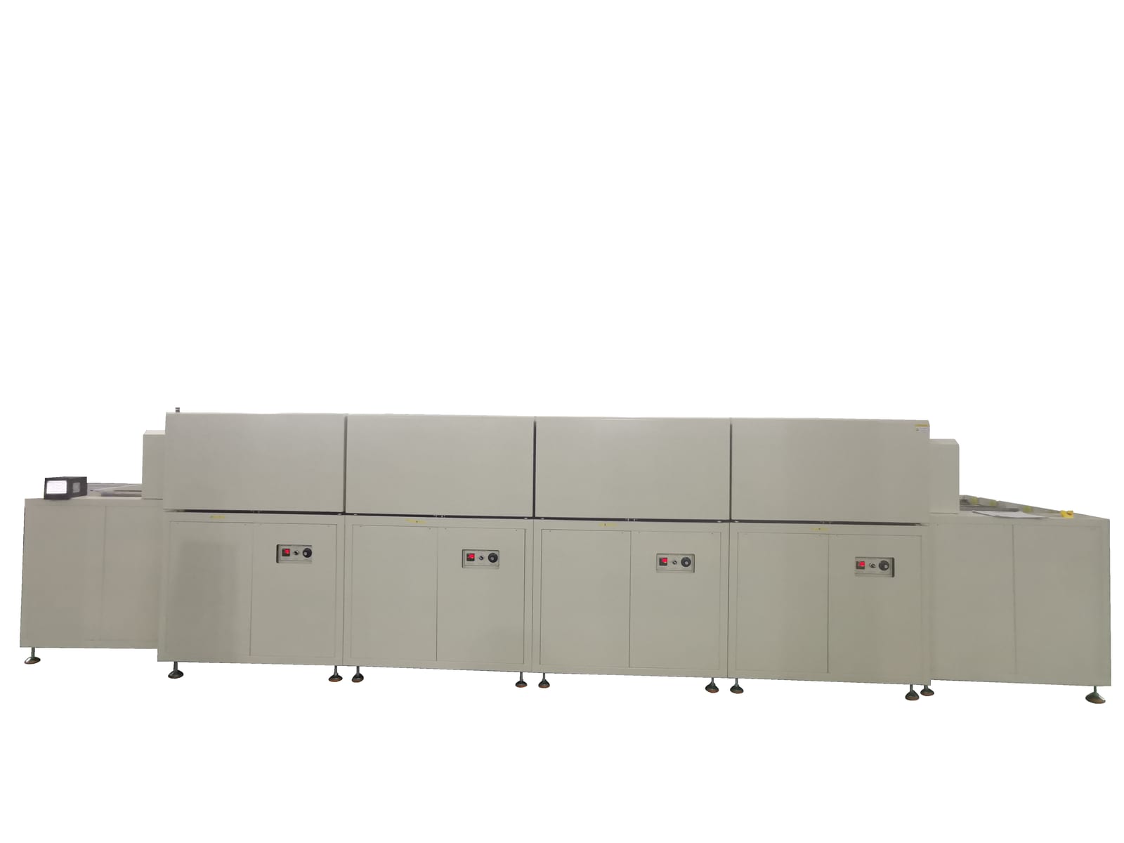
For the first curing stage, the whole board carries 20 products into a tunnel oven for drying and curing. Oven length is configured according to curing time, the temperature is adjustable, and a dedicated carrier is specified for board transport. The second curing stage uses the same tunnel-oven principle after epoxy dispensing.
Epoxy dispensing, terminal crimping and test planning
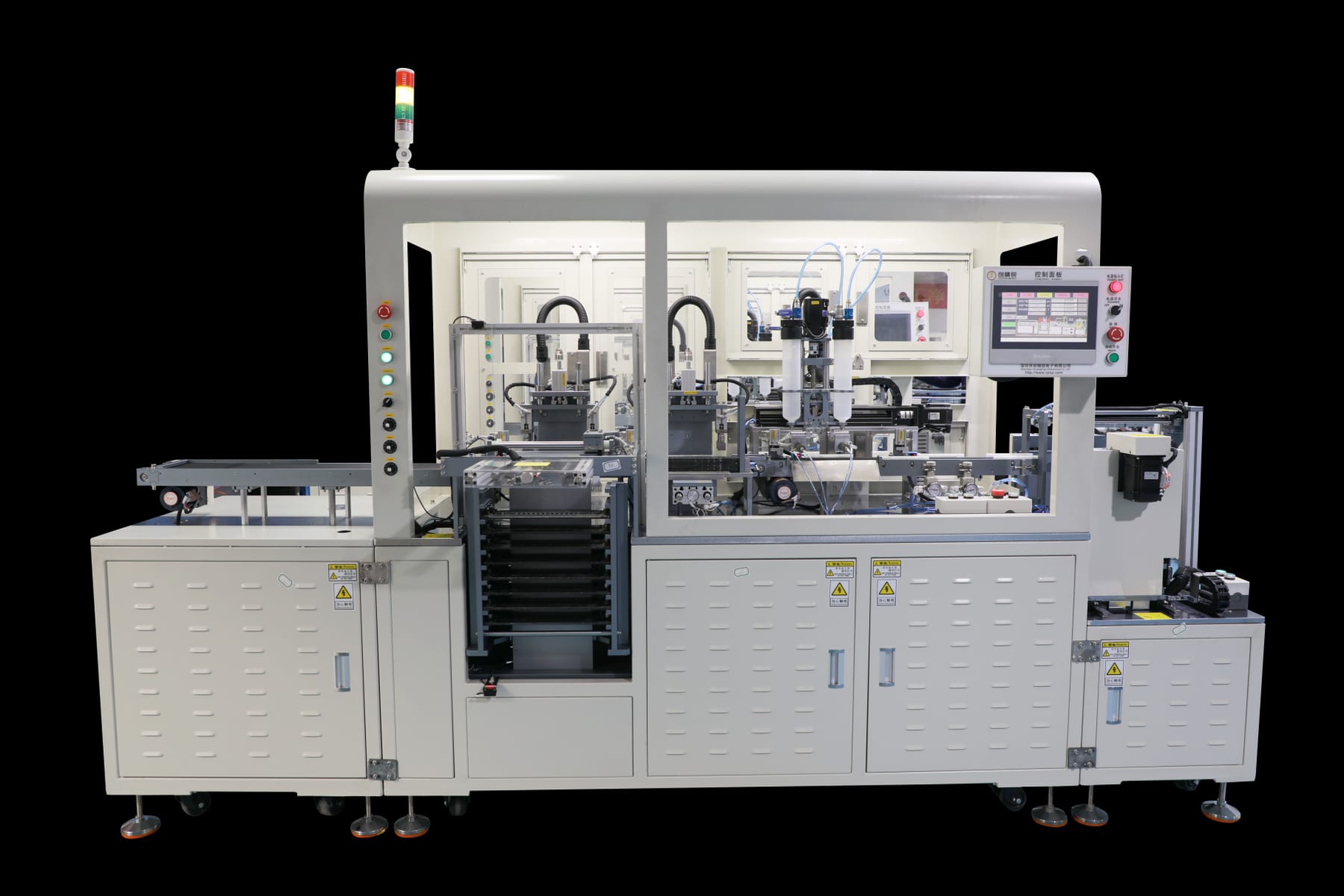
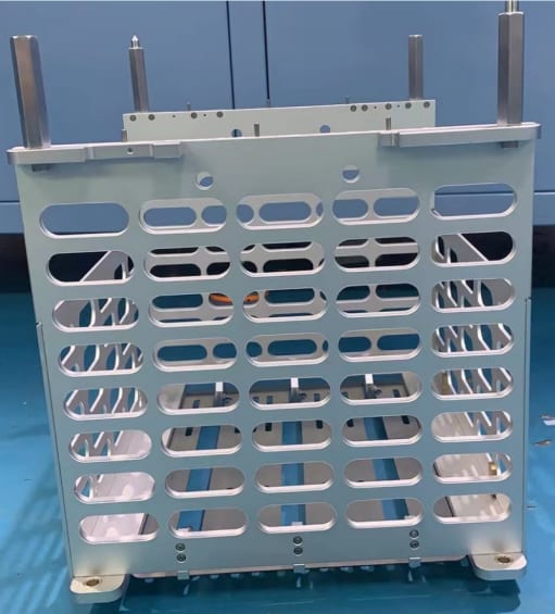
The epoxy dispensing stage uses two dispensing valves and has confirmed capacity of 1,800 to 2,500 PCS/H. For a 20,000-piece daily target, the plan specifies one automatic shell-insertion and dispensing machine plus 1,000 shell-positioning dispensing fixture sets, composed of bottom plate, middle shell-positioning plate and cover plate.
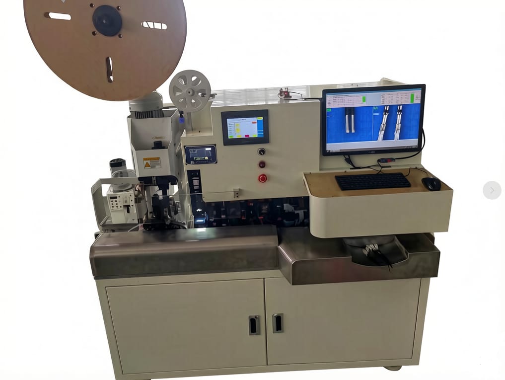
The terminal crimping and shell-insertion machine has a confirmed capacity of 800 PCS/H. We specify two units to meet capacity demand, with one operator watching one machine. The process combines automatic 1P wire stripping, terminal crimping, insertion into the rubber shell and resistance-value detection.
Confirmed planning values
| Area | Confirmed specification |
|---|---|
| Wire cutting and boarding | Five wire-feeding reels; 50 to 1,500 mm wire-length range |
| Wire boarding efficiency | 2,000 to 2,200 PCS/H, depending on wire length |
| Wire board planning | At least 1,000 active boards for a 10-hour day; another 1,000 recommended for the return cycle |
| NTC resistance welding | Dual-station welding; 1,600 to 2,000 PCS/H |
| Optional CCD inspection | 1,800 to 2,400 PCS/H; multi-camera AI visual recognition |
| CCD storage rack | 20 to 30 boards |
| Silicone coating | 10,000 to 14,000 PCS/H |
| Curing board load | 20 products per board |
| Epoxy dispensing | Two dispensing valves; 1,800 to 2,500 PCS/H |
| Dispensing fixtures | 1,000 shell-positioning dispensing fixture sets for 20,000-piece daily planning |
| Terminal crimping and insertion | 800 PCS/H per machine; two units required for capacity demand |
| Equipment-stage staffing | 7 operators for the equipment process sections |
Outcome
Proposed operating result
The resulting concept gives the drive-motor temperature sensor process a linked production route from wire preparation and NTC welding through potting, curing, dispensing, crimping and final testing. It uses confirmed machine capacities to size the front-end and back-end bottlenecks instead of treating every station as the same capacity class.
Quality and data control
The integrated performance-test planning covers head positioning, high-voltage insulation testing, 25 C resistance testing, 85 +/- 1 C high-temperature water-bath resistance testing, data collection, automatic NG picking and buffer discharge. The confirmed test-machine efficiency is 1,800 to 2,000 wires per hour, depending on manual loading speed, with PLC plus host-computer control software and one operator watching the machine.
Project Feedback
Share a short review of this case study or tell us what kind of automation project you want to compare it with.
No published reviews yet.