
Inquiries, partnerships, and case study downloads:sales@robotlyne.com
Inline Dual-Head Screw Fastening Machine
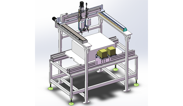
Screw Fastening machine with dual heads, CCD position recognition, tray conveying and configurable M4, M5 and M6 feeders for 600 to 900 PCS UPH.
Project Snapshot
- Client Type
- General Manufacturing Site
- Timeline
- Project dated 2026-04-28
- Deliverables
- Inline dual-head screw fastening layout
- CCD position-recognition and product tray conveying concept
- Screw-feeder configurations for M4, M5 and M6 screws
- Reference dimensions for 1, 2, 3, 4 and 6 feeder groups
Background
Project scope
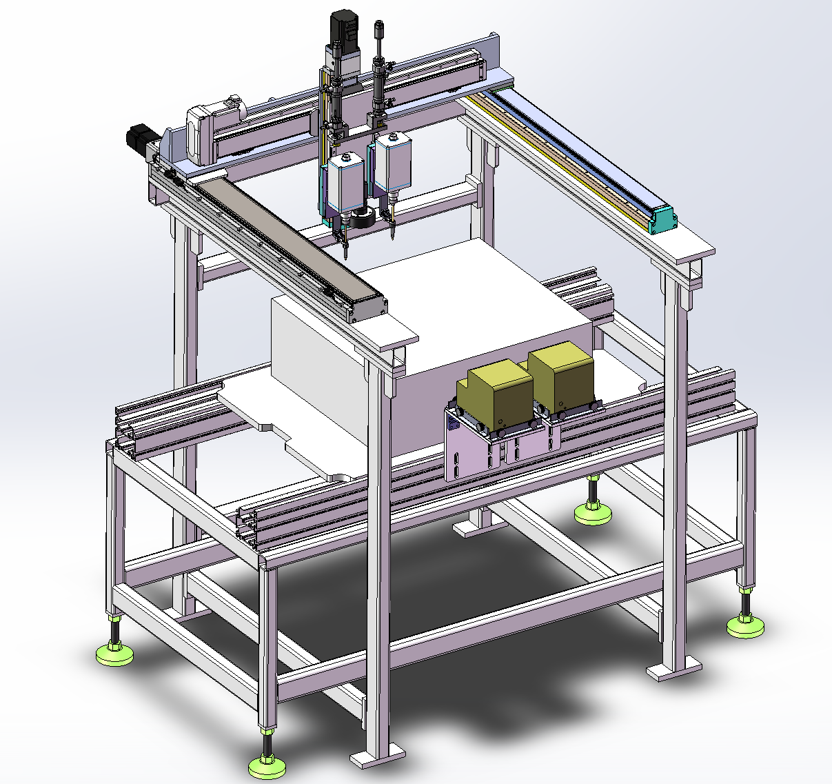
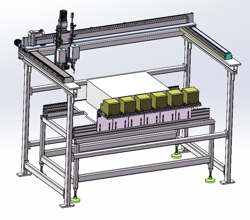
We designed an inline dual-head screw fastening machine for tray-based product assembly. The machine uses X, Y and Z motion, two screw fastening heads, CCD position recognition, product tray conveying and screw feeders configured by station requirement.
The confirmed output reference is 600 to 900 PCS UPH. The project parameter table notes that overall board-level UPH will decrease as the number of screw feeders increases, and that the final value should be determined from actual site conditions. Operator requirement is not specified in the parameter table, so it is not claimed here.
Challenge
Supporting multiple screw specifications
The workstation list includes M4, M5 and M6 screw combinations across different stations. Some stations require one feeder, while others require two, three, four or six feeder groups. The machine therefore needs a layout that can keep the dual-head fastening platform consistent while adapting feeder quantity to the station.
Preserving tray positioning before fastening
Because the product is carried on a tray, the fastening system needs position recognition before locking. The CCD recognition module is used to locate the product before the two fastening heads perform the screwdriving operation.
Approach
Inline fastening layout
The layout combines a product conveying tray, two fastening heads, a CCD recognition point, X/Y/Z motion axes and screw feeder groups positioned around the fastening area.
Feeder configurations
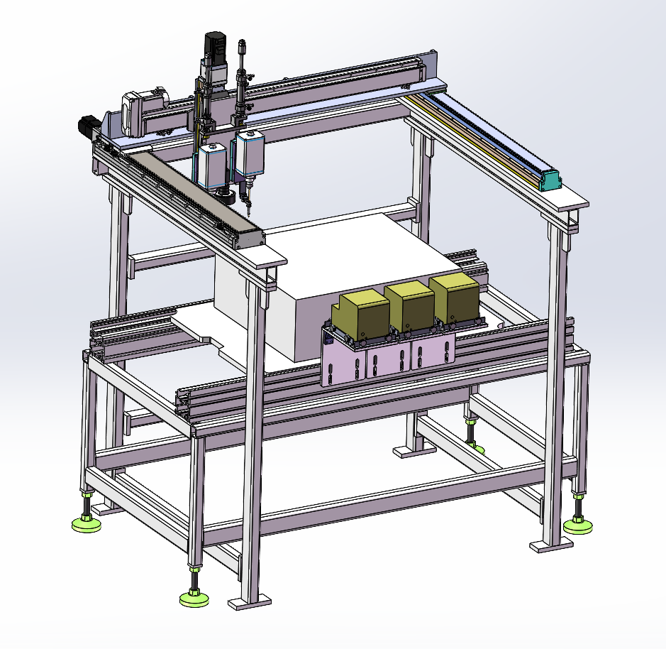
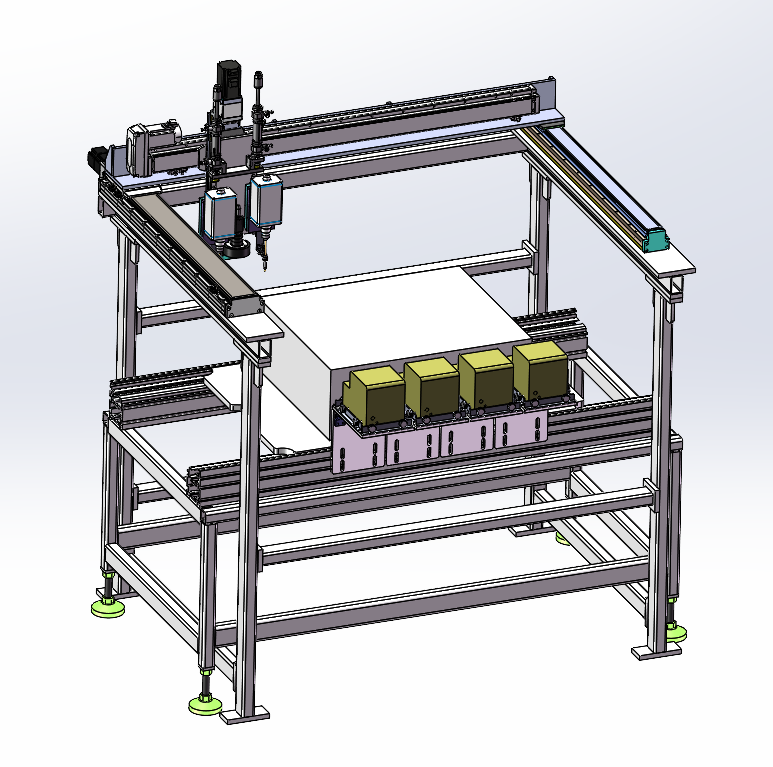
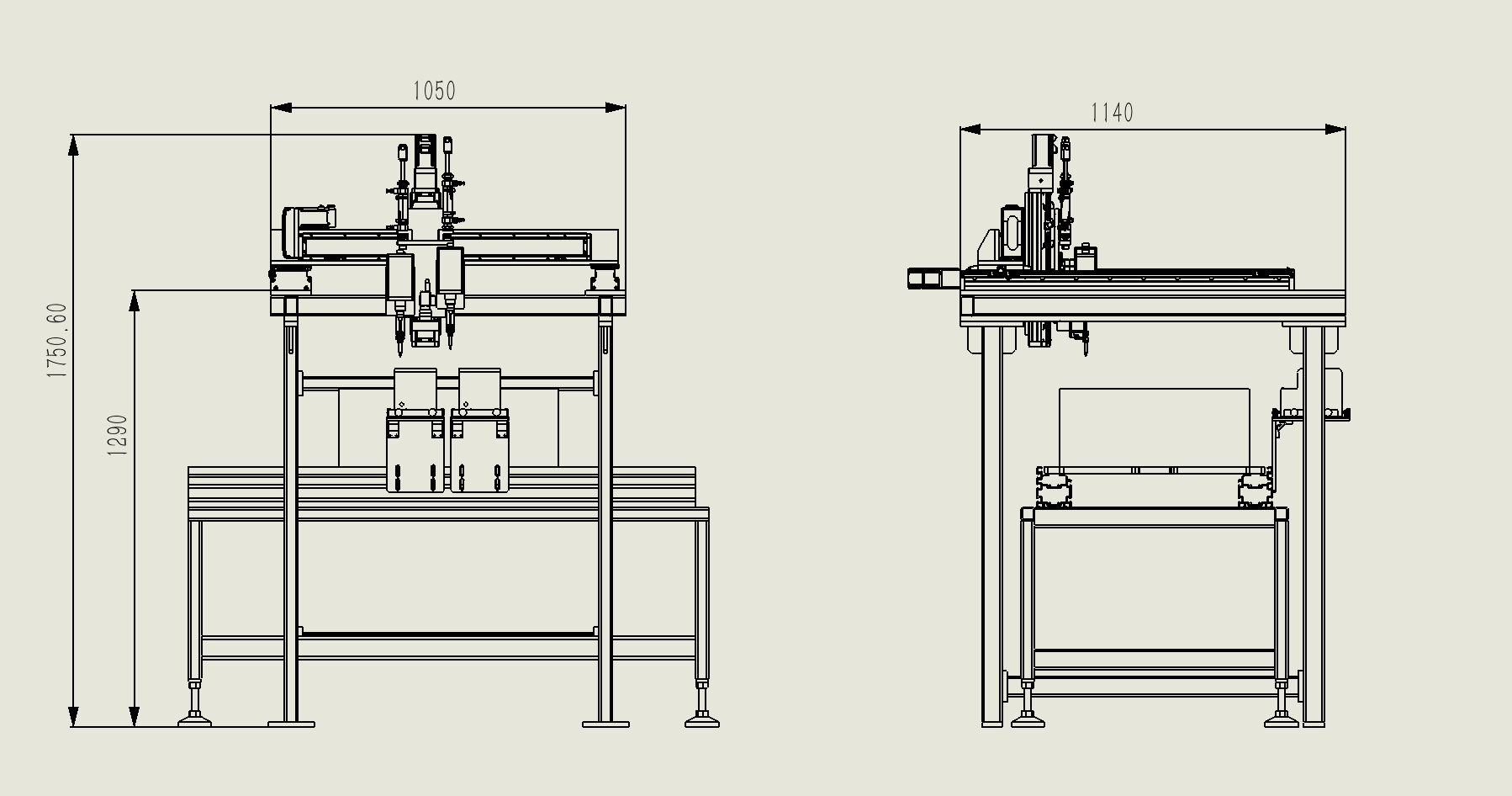
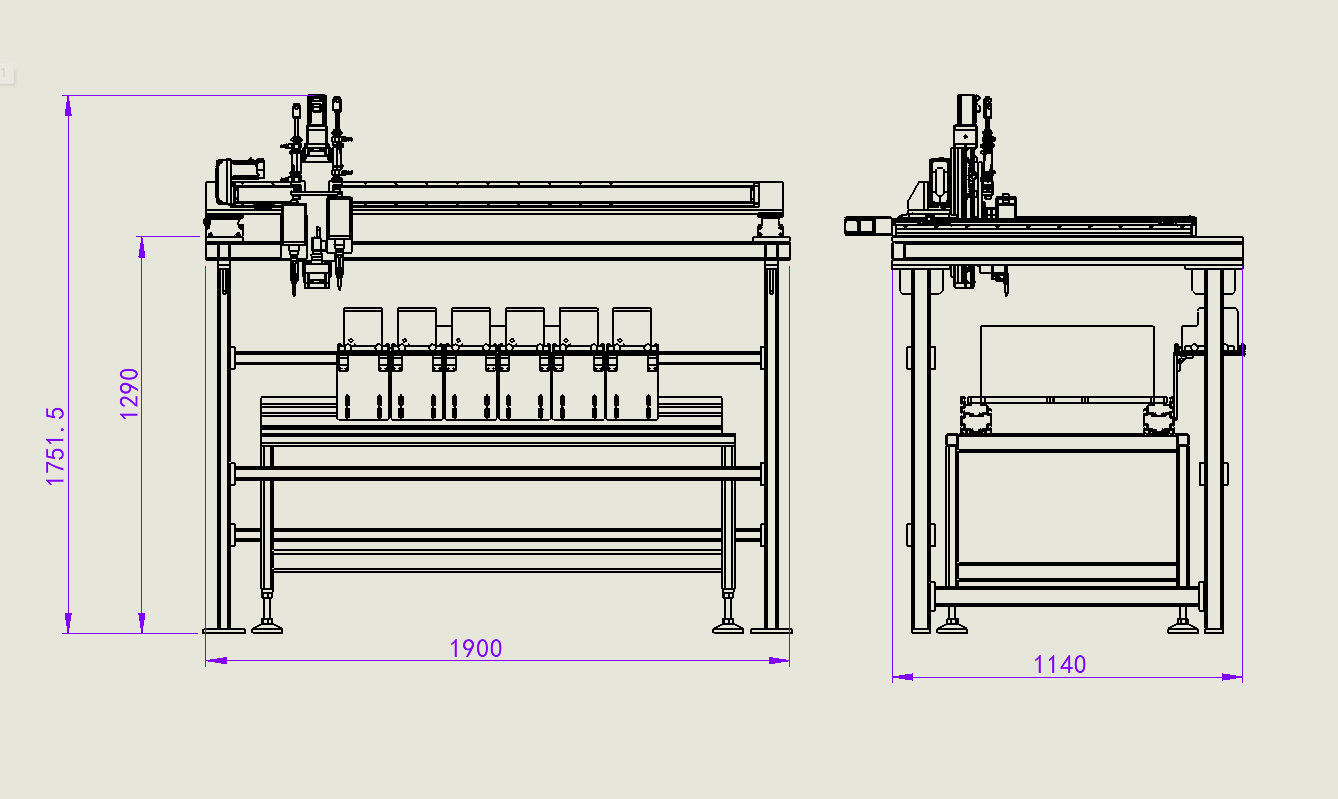
The confirmed station table defines station-based feeder counts and reference feeder-module dimensions. Stations using 1 or 2 feeders share a 1050 x 1140 x 1752 mm reference size. Higher feeder counts use larger footprints.
| Station | Screw specification | Feeder count | Reference size |
|---|---|---|---|
| 2-1 | M4, M5 | 1 | 1050 x 1140 x 1752 mm |
| 8-1 | M4, M5 | 1 | 1050 x 1140 x 1752 mm |
| 9-1 | M4, M5 | 2 | 1050 x 1140 x 1752 mm |
| 12-1 | M4, M6 | 2 | 1050 x 1140 x 1752 mm |
| 13-1 | M4, M5 | 1 | 1050 x 1140 x 1752 mm |
| 10-1 | M5, M6 | 2 | 1050 x 1140 x 1752 mm |
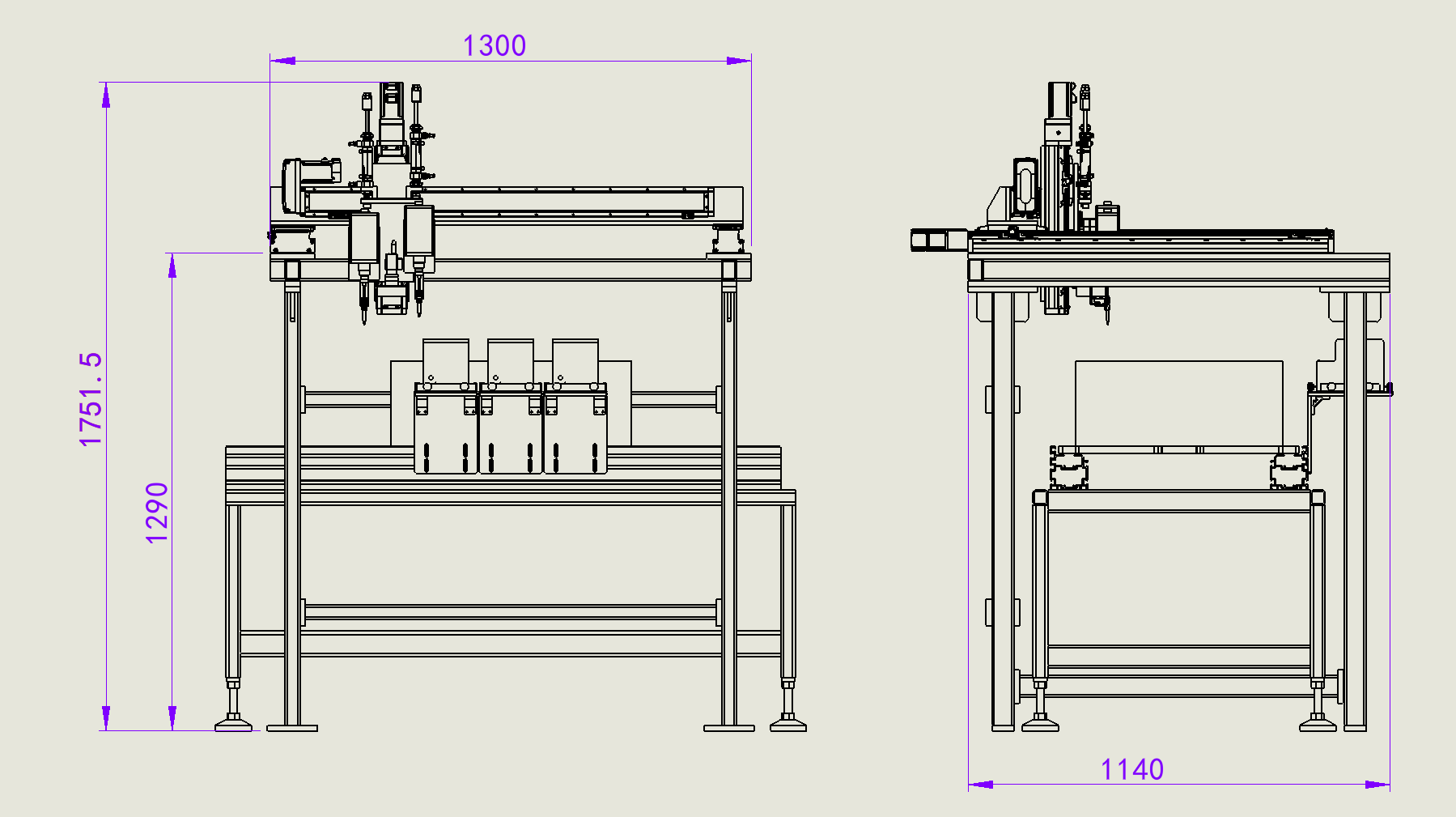
| 3-1 | M4, M6 | 3 | 1300 x 1140 x 1752 mm |
| 7-1 | M5, M6 | 6 | 1900 x 1140 x 1752 mm |
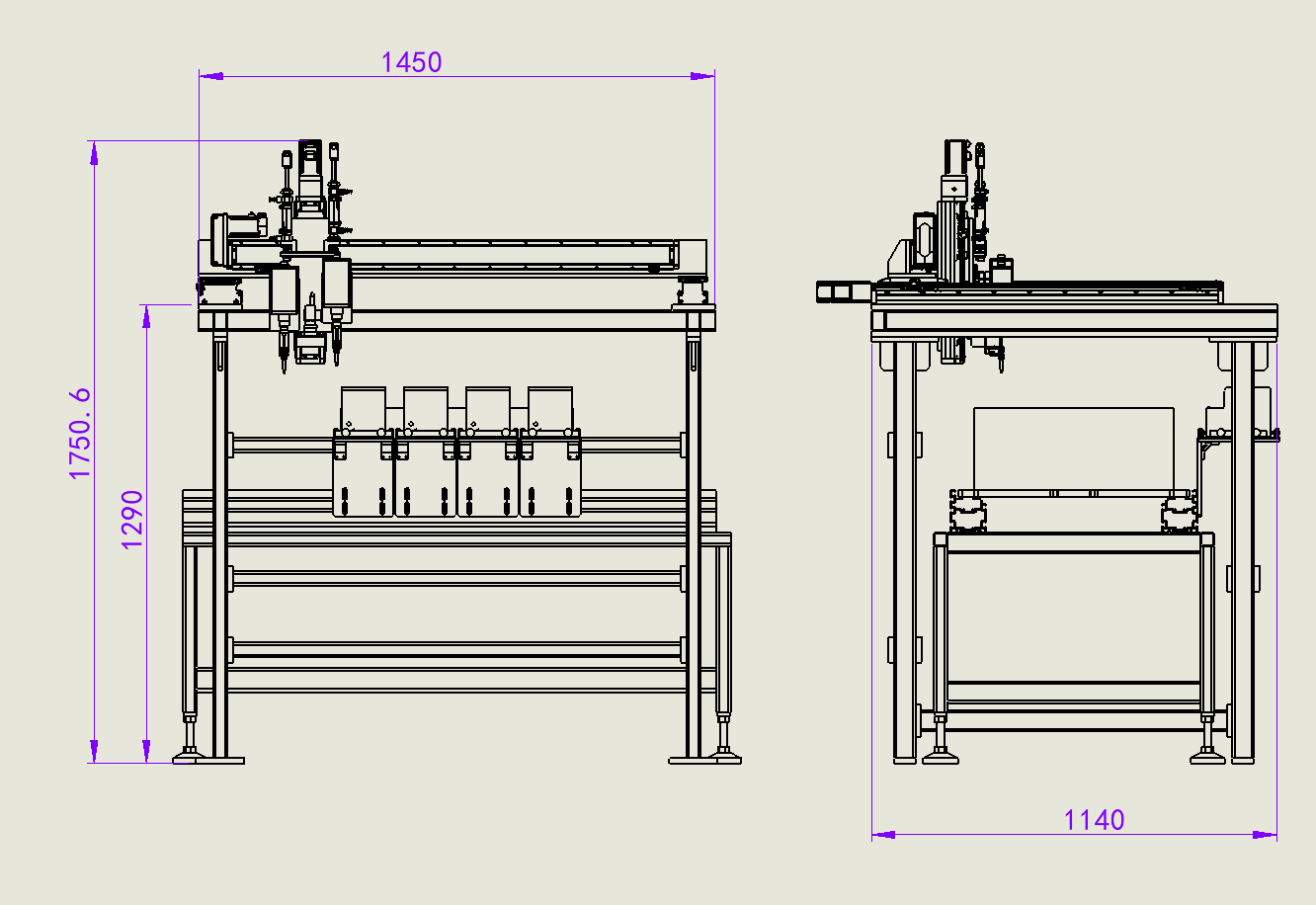
| 11-1 | M5, M6 | 4 | 1450 x 1140 x 1752 mm |
Reference dimension set
The detailed feeder-dimension drawings provide module envelopes for the 1/2 feeder, 3 feeder, 4 feeder and 6 feeder arrangements. The general parameter table refers back to these detailed dimension drawings for L x W x H sizing.
Reference parameters
| Item | Confirmed specification |
|---|---|
| Air supply | 0.4 to 0.6 MPa |
| Power supply | AC220V |
| Planned capacity | 600 to 900 PCS UPH |
| Capacity note | Board-level UPH decreases as feeder quantity increases; final value depends on site conditions |
| Control system | PLC |
| Operator requirement | Not specified in the project parameter table |
Outcome
Proposed operating result
The proposed machine gives the screw fastening process a modular inline platform. Product trays move through the fastening area, CCD recognition supports product positioning, and the dual-head fastening system works with station-specific feeder groups.
Process value
The process value is configurable screw feeding around a consistent dual-head fastening core. The same equipment concept can support M4, M5 and M6 fastening requirements with 1, 2, 3, 4 or 6 feeder groups, while the confirmed planning range remains 600 to 900 PCS UPH subject to actual feeder count and site conditions. Commercial return figures are not included in the project data, so ROI is left unclaimed.
Project Feedback
Share a short review of this case study or tell us what kind of automation project you want to compare it with.
No published reviews yet.